Chapter 1 Installation Of UPS Rack System 16
J5
BFP_C
BFP_S
BFP_O
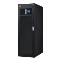
Fig.
1-5
: Connections of output dry relay contacts
Position Name Meaning
J5.2 BFP_O Bypass backfeed protection - relay normally open.Closed when bypass SCR is shorted.
J5.3 BFP_S Bypass backfeed protection - common
J5.4 BFP_C Bypass backfeed protection - relay normally closed.Opened when bypass SCR is shorted.
Tab.
1-5: Relay dry contact output port
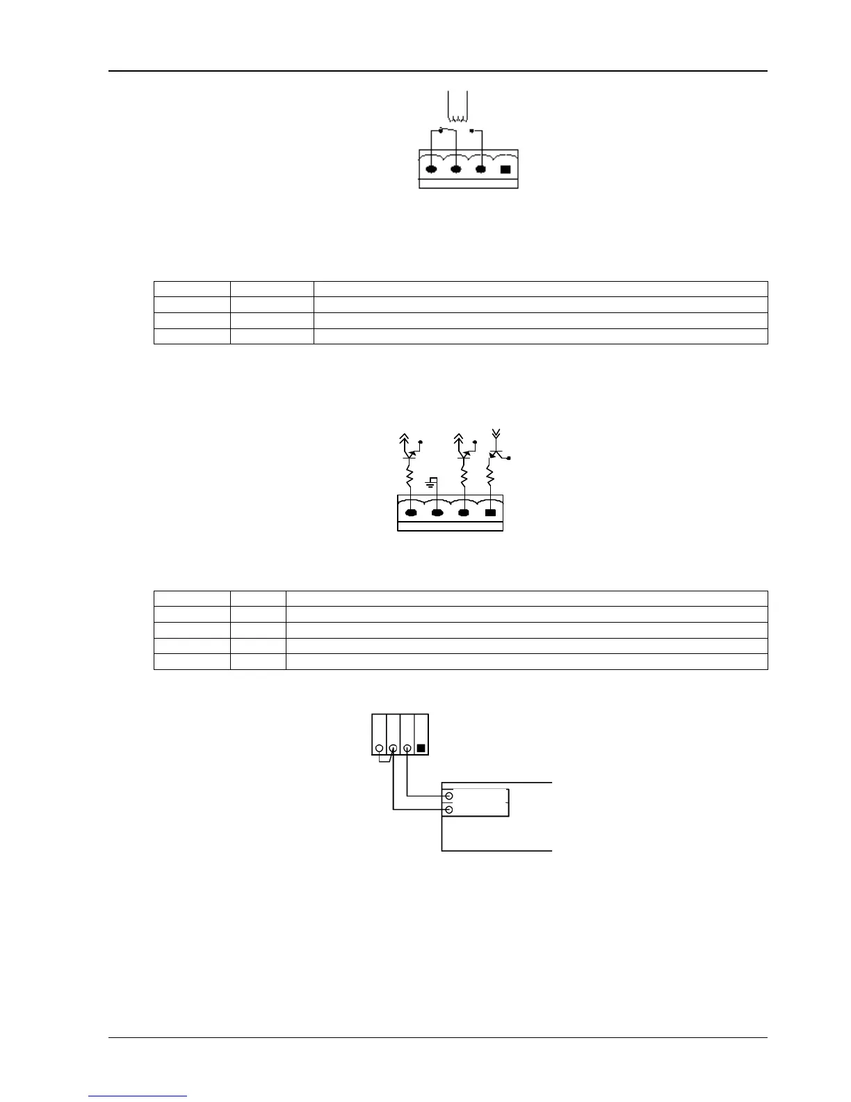
1.7.3 External Battery Circuit Breaker Interface (J6)
12V
OL
GND
FB
DRV
J6
12V
12V
Fig.
1-6: External BCB interface
Position Name Descriptions
J6.1 DRV BCB drive signal (Hig = BCB can be closed)
J6.2 FB BCB contact status (Closed = BCB is closed)
J6.3 GND Power supply GND
J6.4 OL BCB online-Input (normally open): This pin is closed to gnd when BCB interface signal is connected
Tab.
1-6: External battery circuit breaker interface
电池开关
BCB
J10
OL
GND
FB
DRV
Aux-N.O.
Aux-N.O.
J6
Aux_N.O.
Aux_N.O.
BCB
Fig.
1-7: Connection of BCB interface
1.7.4 Other input Interface (J7)
Input dry contacts for environment detection and battery ground fault detection are provided by interface J7