26 Chapter 2 Installation Of UPS Rack System And Parallel System
Note: in Fig.
3-3, X2 is the dry contact and parallel signal board
3.3 Dual-Bus System
3.3.1 Installation
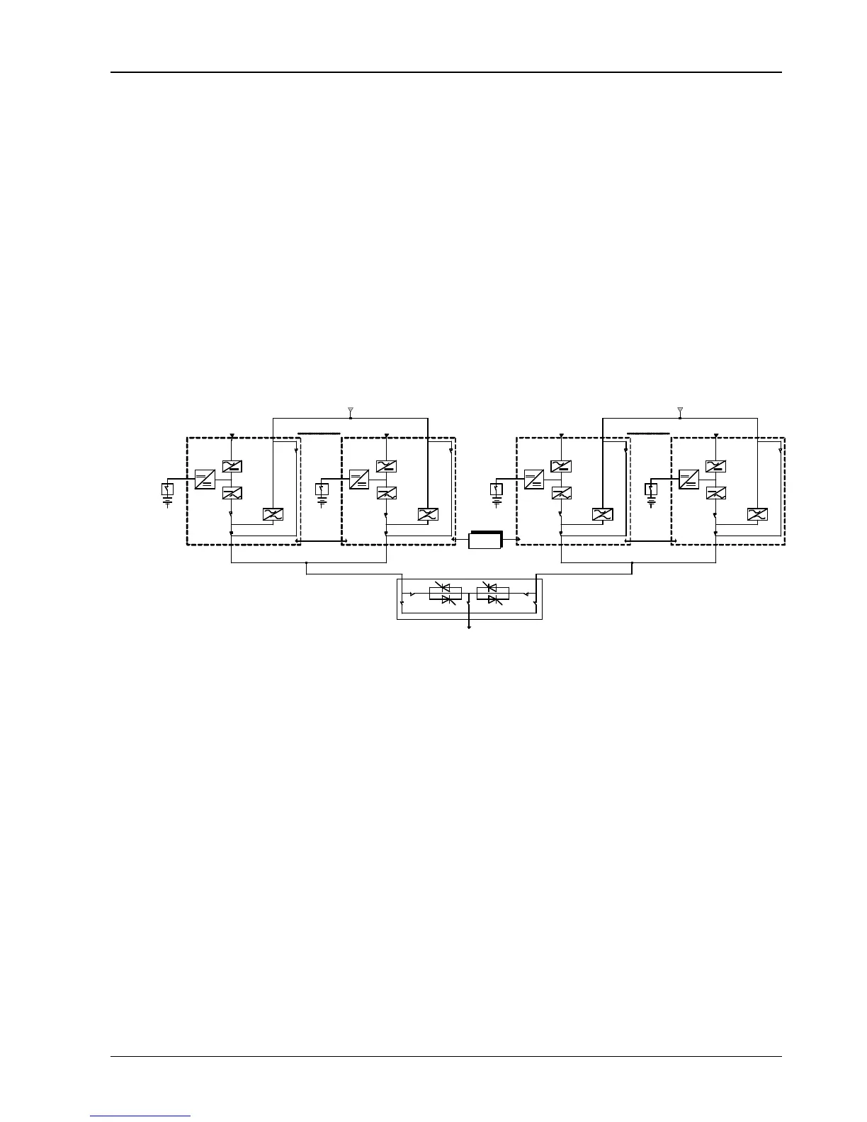
The dual bus system (DBS) consists of two independent UPS rack module systems and each UPS system consists
of one or more UPS power modules and a bypass power module. The dual bus system is configured for high
availability and is suitable for powering the load with dual inputs. If the load is single-input load, the static transfer
switch and LBS control is recommended to maintain both UPS outputs synchronized for uninterrupted transfers.
Please install the system according to the installation descriptions for different system configurations.
All the UPS rack modules should be installed side by side, and the cables should be connected according to the
following descriptions.
The LBS control synchronizes makes the outputs of two UPS rack modules (or parallel systems) synchronized. One
system is set as the master unit and the other system is set as slave unit. The LBS enables the load to have two
independent UPS sources.
UPS1 UPS 6 UPS1 UPS 6
LBS
STS
UPS1 UPS UPS1 UPS
LBS
Connect to load
Input rectifier
Input rectifier Input rectifier
parallel
control
cable
parallel
control
cable
Bypass
Bypass
Input rectifier
Fig.
3-4:
Typical dual bus system (with static bypass switch LBS)
3.3.2 External Protective Devices
Refer to
Chapter 1 Installation
3.3.3 Power Cables
The power cable connection of the parallel system is similar to that of the UPS module system. If the bypass input
and rectifier input share the same neutral terminal, and if an RCD protective device is installed at the input, then the
RCD device must be installed before the input cables are connected to the neutral terminal. Refer to
Chapter 1
Installation. Notes: keep bypass currents balanced on bypass mode.
3.3.4 Control Cables
For LIEBERT APM to LIEBERT APM dual-bus system, use the optional LBS cables to connect any two digital LBS
interfaces of the two paralleled UPS systems, as shown in Fig.
3-5.