Chapter 1 Installation Of UPS Rack System 18
Q3: Battery temperature sensor must be purchased separately; the part number of the battery temperature sensor is
at the beginning of this document.
Q4: J8 port is used to connect internal battery temperature sensor and external battery temperature sensor.
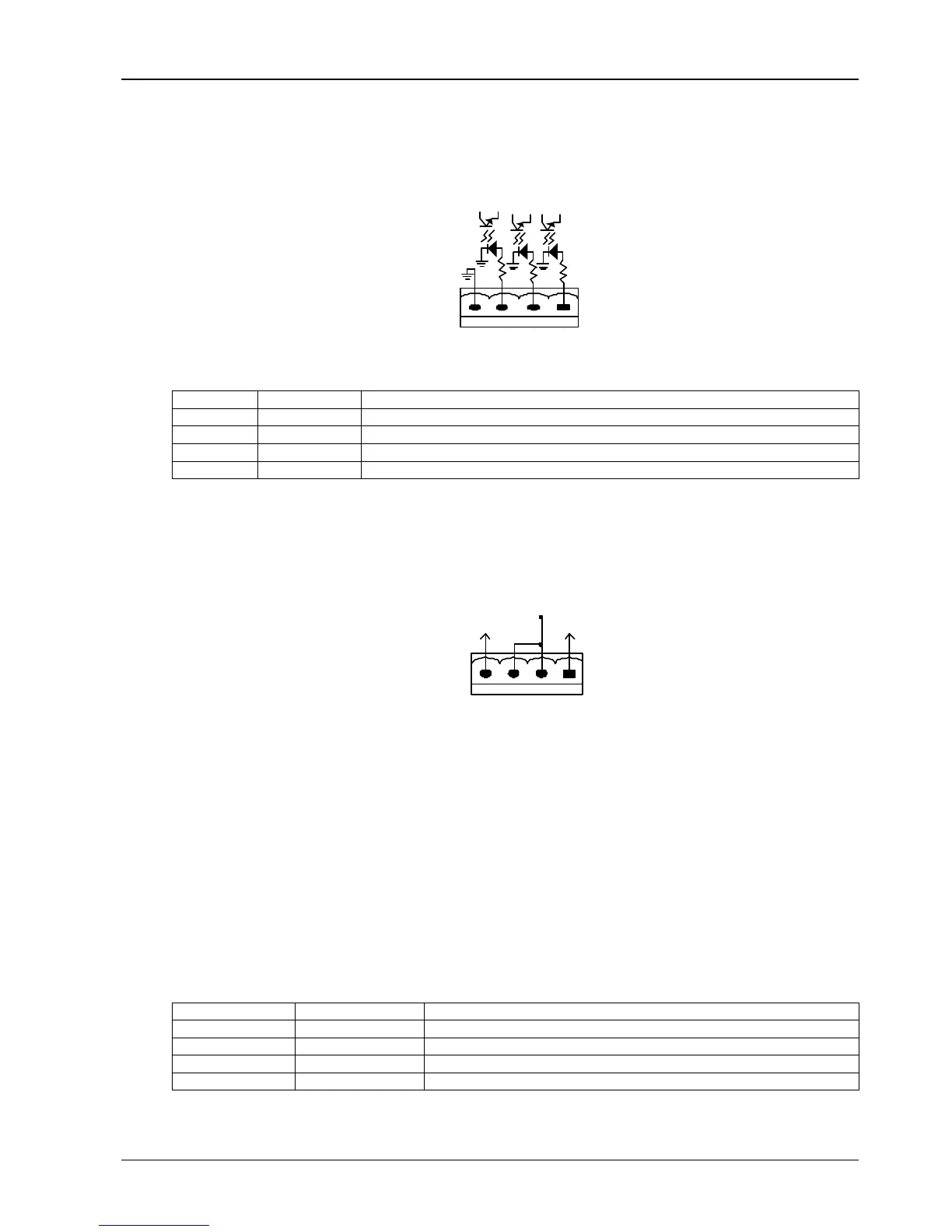
1.7.6 Internal and External Maintenance Bypass Interface (J9)
EXT-S
CAB-S
CAB-S
J9
EXT_Q3
IN_S
GND
EXT_OUT
Position Name Meaning
J9.1 EXT_ Q3 External Maintenance Bypass input switch status [Normally Closed]
J9.2 IN__S Internal Maintenance Bypass switch status [Normally Closed]
J9.3 EXT _OUT
External Maintenance Bypass output switch status [Normally Closed]
J9.4 GND Power supply GND
Tab.
1-8: External maintenance bypass cabinet Interface
Note 1: These contacts cannot be active unless they are set via software.
1.7.7 EPO Input Port (J10)
J10
+12V
EPO_NO
+12V
+12V
EPO_NC
Fig.
1-10
: Connections of EPO
The UPS has an Emergency Power OFF (EPO) function. This function can be activated by pressing a button on the
control panel of the UPS or through a remote contact provided by the user. The EPO pushbutton is protected by a
hinged plastic cover.
As shown in Fig.
1-10 J10 is the input interface for remote EPO. The EPO is triggered when shorting pin 3 and pin 4
of J10, or opening pin 1 and pin 2.
If external emergency stop functionality is required, it is connected via the reserved terminals of pin 1 and pin 2 or pin
3 and pin 4 of J10. The external emergency stop interface needs to use shielded cables to connect to the normally
open/closed' remote stop switch between these two pins (refer to Fig.
1-4, and Tab.
1-9). If this interface is not used,
then pin 3 and pin 4 of J10 must be open, or pin 1 and pin 2 of J10 must be connected.
Position Name Meaning
J10.1 EPO_NC EPO is activated when it is disconnected from J10.2
J10.2 EPO_NC EPO is activated when it is disconnected from J10.1
J10.3 EPO_NO EPO is activated when it is short circuited with J10.4
J10.4 EPO_NO EPO is activated when it is short circuited with J10.3
Tab.
1-9: EPO input dry contact relay