NOTE: If your system does not contain a redundant module, you may need to manually place the UPS
into manual bypass before removing modules to avoid accidental loss of output power for the
connected equipment.
3. Use a Phillips-head screwdriver to remove the screws from the 2securing holes.
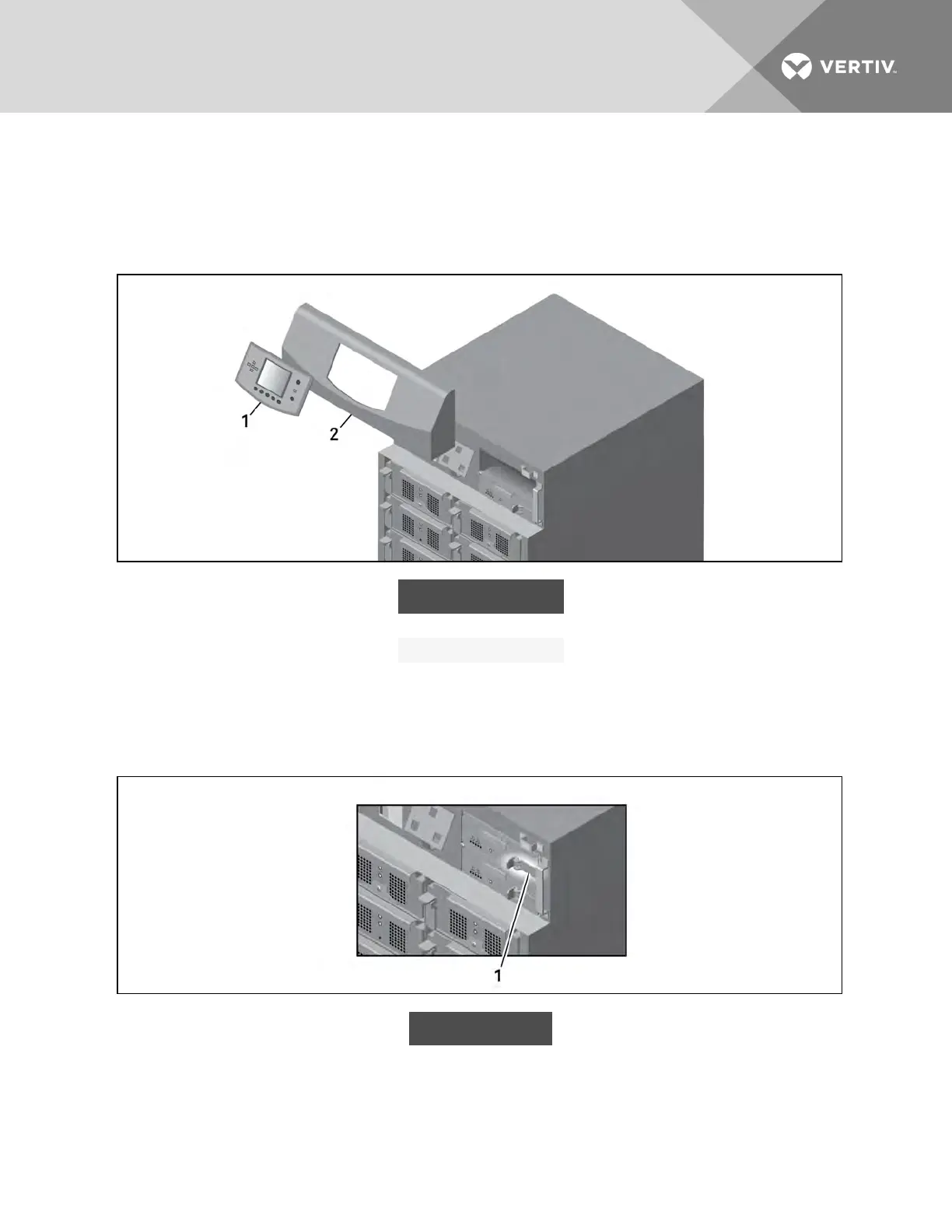
Figure 6.2 Remove display bezel and user-interface module
ITEM DESCRIPTION
1 User-interface module
2 Display bezel
4. Pull out the lock lever slightly and pull to the left (see Figure 6.3 below), then wait a view
seconds before continuing.
5. Making sure to support the module, slide it completely out of its control bay.
Figure 6.3 Releasing the lock lever
ITEM DESCRIPTION
1 Lock lever
Vertiv | Liebert® APS™ Installer/User Guide | 74