6
Liebert
®
PDX, EconoPhase Version - UM - 265133 - 29.08.2019
1.8 - Description of Liebert
®
EconoPhase Operation
The Liebert
®
EconoPhase unit enables the Liebert
®
PDX system
to operate in any of three modes to control temperature, depending
on the outdoor temperature and the load.
• Compressor Mode
• Pump Mode
• Mixed Mode
When the outdoor temperature becomes low enough to provide
the required temperature dierence between the inside air and
the outside air, there is no need to compress the refrigerant to a
higher pressure/temperature. When the outdoor temperature is
low enough, the system switches from Compressor Mode to Pump
Mode or to Mixed Mode.
• Compressor Mode: All available compressors may be used
to maintain the control temperature. All the available Liebert
®
EconoPhase pumps are O. The control will typically run in
this mode when the load and temperatures are such that full
or partial Liebert
®
EconoPhase operation is not possible, or
because certain pumps have experienced alarms.
• Pump Mode: All of the available pumps may be used to
maintain the Control Temperature. All the compressors in the
system are O. The control will typically run in this mode when
load and temperatures permit.
• Mixed Mode: The pump in Circuit 1 is On and the compressor(s)
in Circuit 2 is On. Some systems may not have Mixed Mode
capability, depending on the manufacture date. Contact the
factory to inquire about a software upgrade.
1.8.1 EconoPhase Control
EconoPhase operation has three main controlled parameters:
• return or supply air temperature control
• refrigerant temperature
• pump pressure dierential (outlet pressure - inlet pressure)
Room Temperature
When the system is in Pump Mode, the room temperature is
controlled by modulating the pump speed with a variable frequency
drive. The load requirement will determine if one pump or two
are needed. Figure 8 shows the sequence of operation in terms
of pump speed. Minimum speed is 45% and maximum speed is
100%. See Table 2 for more detail on the events shown in Figure 8
and the conditions that trigger action.
The pump startup routine calls for a start speed of 80%. The pump
will run for up to 60 seconds at 80% with the EEV at 60% while
waiting on the pump pressure dierential to reach at least 0.83 bar
to indicate that ow has been established. If the pump establishes
ow, the speed will change from 80% to the required control speed
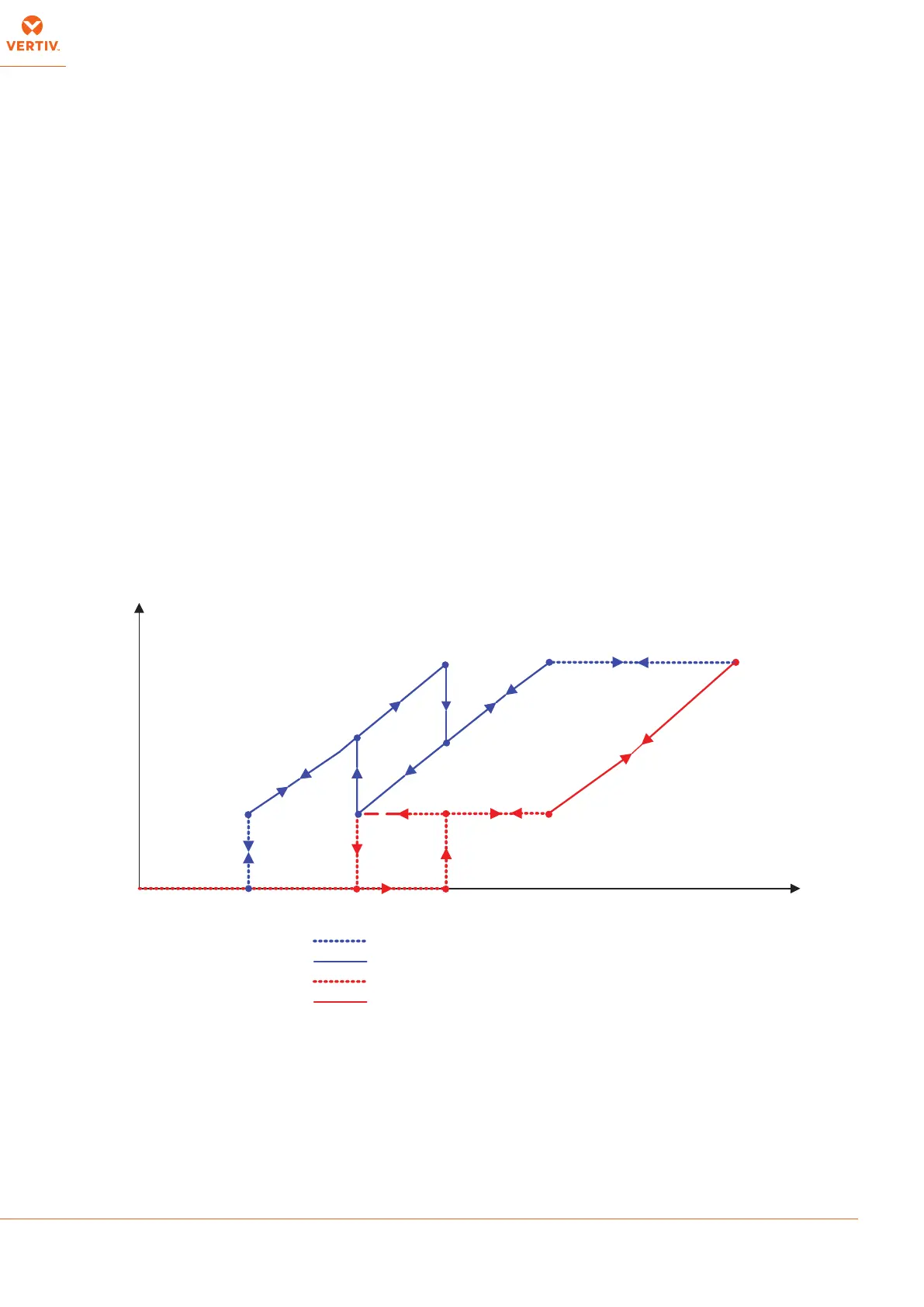
as shown on the curves in Figure 6.
Fig.6 - Two-circuit pump control
E
I
C
H
F
K
J
A
B
100%75%55%40%20%0
Minimum
Pump
Speed
Maximum
Pump
Speed
Pump
Speed
y
x
Capacity
Pump 2
L
G
D
Pump 1
Pump 2 under manual control
Pump 2 under PID control
Pump 1 under manual control
Pump 1 under PID control