15
Liebert
®
PDX, EconoPhase Version - UM - 265133 - 29.08.2019
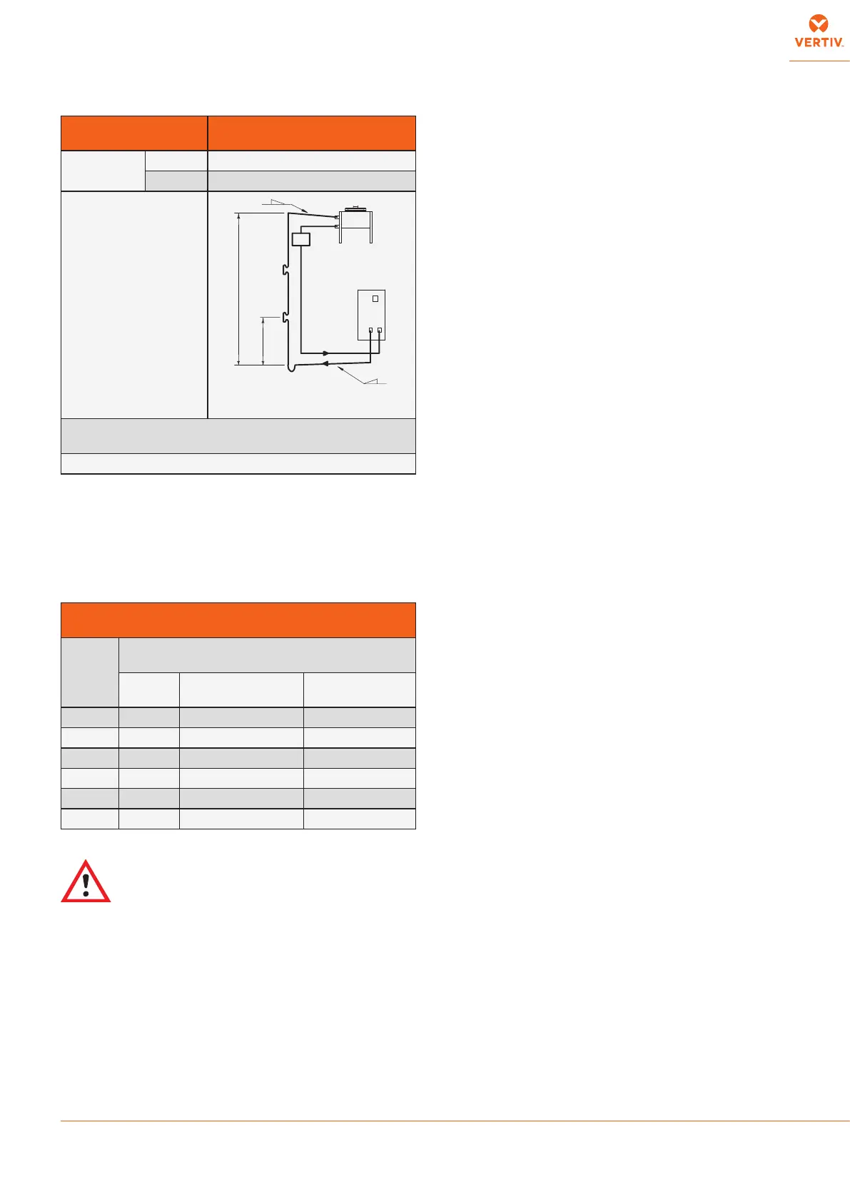
Tab. 5 - Condenser positioning
4.1.2 - Pipe diameter
The diameters of the connecting pipes between the conditioner and
the condensing unit listed in Tab. d must be respected, otherwise
the guarantee becomes invalid..
Tab. 6 - Pipe diameters (room unit - remote condenser - pump
module)
WARNING: Due to higher pressure with R410A, use
copper pipes and copper ttings with thickness 1.5mm
when external pipe diameters are higher than 18mm
(22 and 28mm)
STANDARD PIPE DIAMETERS
(Valid for equivalent lengths up to 100 m)
MOD.
copper tube external diametre x thickness [mm]
R410A
Gas
Liquid from
condenser to PRE
Liquid from PRE
to room unit
PX082 28 x 1.5 28 x 1.5 22 x 1.5
PX094 28 x 1.5 28 x 1.5 22 x 1.5
PX104 28 x 1.5 28 x 1.5 22 x 1.5
PX120 28 x 1.5 28 x 1.5 22 x 1.5
PX150 35 x 1.5 35 x 1.5 28 x 1.5
PX165 35 x 1.5 35 x 1.5 28 x 1.5
CONDENSER
POSITION
CONDENSER ABOVE
CONDITIONER
INSULATION
gas required
liq. required
LAYOUT
(*) Oil traps every 6 m of
vertical piping
(*) Oil traps every 6 m of vertical pipping. Create an oil trap on
the horizonthal discharge line before each lift.
(**) See paragraph 1.9 - Operating limits
6 m
(see *)
gas
liquid
room unit
PRE
4.1.3 - Installing pipelines
THE FOLLOWING OPERATIONS MUST BE CARRIED OUT BY
AN EXPERIENCED REFRIGERATION TECHNICIAN.
NOTICE:
The discharge operation of the room unit pressurized with
helium (at 2 bar) and the unbrazing of the bottoms from
the connections must be carried out as last operations,
immediately followed by the connection and emptying of the
whole system.
1. Lay the piping, taking note of the following:
• Welding:
• All joints must be braze-welded.
• Avoid butt welds by using sleeves or enlarging one
of the pipes using a pipe opener.
• Use silver-based solders and the correct apparatus.
• Guarantee a correct weld as a refrigerant leak, or
a faulty weld which leads to a leak later on, can
seriously damage the air conditioner.
• Always use large-radius curves (bending radius at least
equal to pipe diameter). Bend the pipes as follows:
• soft copper: by hand or bending device.
• hard copper: use preformed curves. Do not overheat
the pipes when welding so as to minimize oxidation.
2. Connect the pipes to the condenser:
• Condensers with butt-welded pipe connections: cut the
pipe, enlarge it and weld it to the pipeline.
• Condensers with threaded tap connections: ange the
pipes and connect.
RESPECT THE DIRECTION OF REFRIGERANT FLOW
(SEE LABELS ON REFRIGERANT CONNECTIONS).
3. Wash out the pipelines as follows:
a. Plug up the free ends of the pipes.
b. Connect a helium or nitrogen cylinder, tted with a
reducer (max. pressure 10 bar), to the ¼” SAE Schrader
valve of the condenser.
c. Pressurize the pipes with helium or nitrogen.
d. Unplug the pipes instantaneously.
e. Repeat a) - d) several times.
THIS OPERATION IS IMPORTANT TO AVOID REFRIGERANT
FILTER CLOGGING, ESPECIALLY WHEN HARD COPPER
PIPING IS USED.
4. Open all the room unit shut- o valve.
5. Discharge the room unit pressurized with helium (at 2 bar)
opening the charge valves so that all the branches of the circuit
are discharged (e.g. on the receiver, on the low pressure side
and on the compressor delivery).
6. Unbraze the bottoms from the connections of the room unit.
7. Fix (weld) the pipes to the connections on the air conditioner.
8. Connect the refrigerant safety valve to the outdoor with a
copper pipe sized in order to satisfy the requirements of
EN13136 (i.e. till 10m length, i 26mm).