Enclosure C - Installation drawings
C - 1 Liebert
®
PDX, EconoPhase Version - UM - 265133 - 29.08.2019
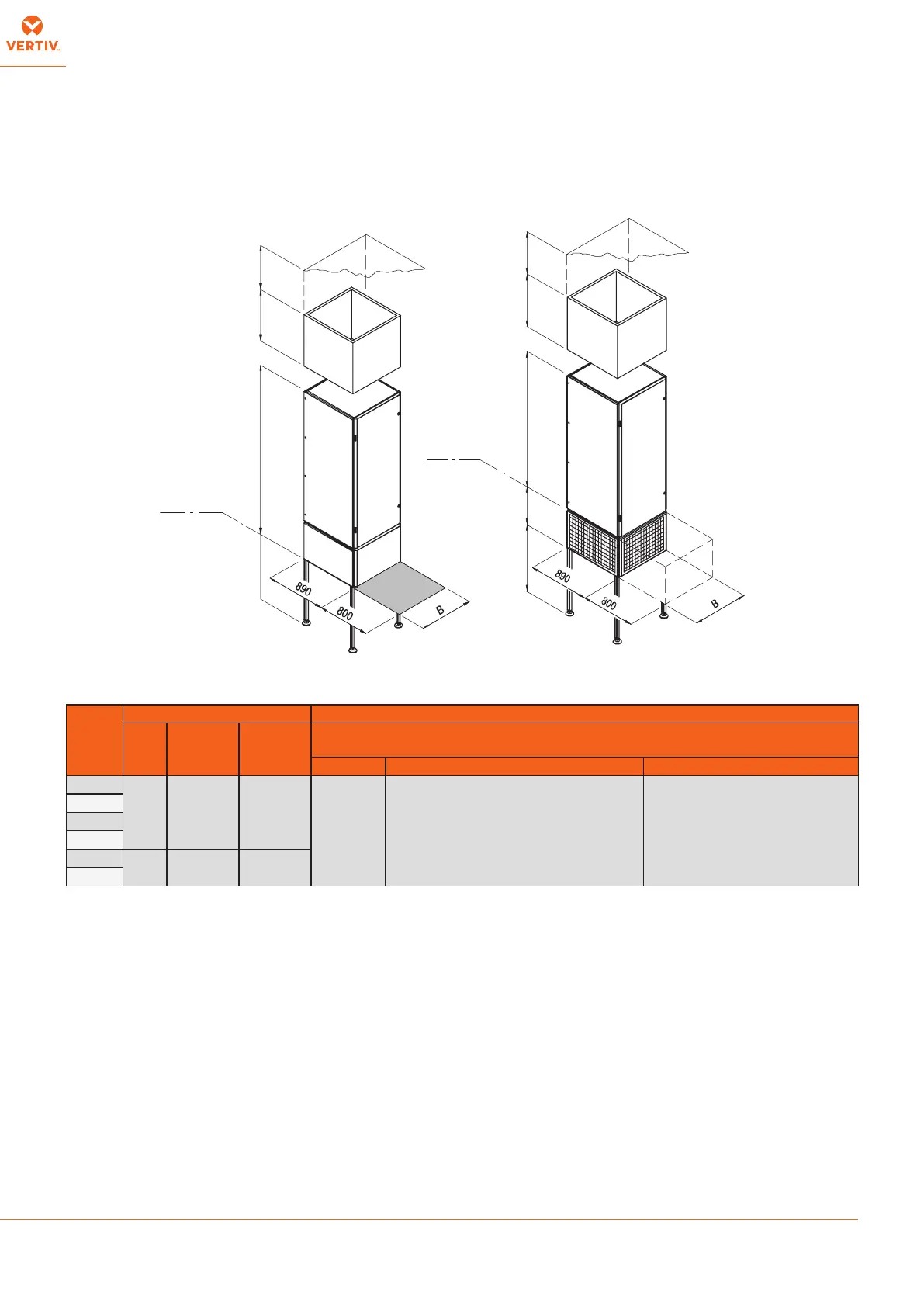
Fig. 1 Overall dimensions and Service Area
Tab. 1 - Overall dimensions - Service area (referring to Fig. 1)
F (free space between unit bottom and basement): max. 800 mm (base frame/legs kit availability)
min. 600mm (to get declared performances)
min. 300mm (minimum working conditions)
G (free space between ceiling and unit top or plenum top if installed): min. 600mm (to get declared performances)
min. 300mm (minimum working conditions)
* In Downow Up units with predisposition for damper and plenum installation (digit 18 = H or L) the unit is shipped with a connecting ange 50 mm high xed on the unit top, so the unit is 50 mm
higher. If required, the ange can be removed by unscrewing the xing screws (removing the side panel to access the screws head) and repositioned later.
D
A*
D
E*
600
MAX 800
Floor
Level
Floor
Level
F
G
G
Models
Unit Options
B
[mm]
Downow
Up
A* [mm]
Downow
Down
E* [mm]
AVAILABLE PLENUM HEIGHTS: D
[mm]
Plenum Plenum for silencing cartridges Plenum for high eciency lters
PX082
2550 1970* 1370*
500- 600-
700- 800-
900
600- 900 600- 900
PX094
PX104
PX120
PX150
3350 2570 1970
PX165