19
Liebert
®
PDX, EconoPhase Version - UM - 265133 - 29.08.2019
• Right side: internal low voltage eld wiring pathways
• Left side: internal high voltage eld wiring pathways
• Use the cable bushing on the back of the panel to get into the
electrical panel.
• Use cable tie to x the power and low voltage cable to the
electrical panel.
For cable entrance holes details see Enclosure D.
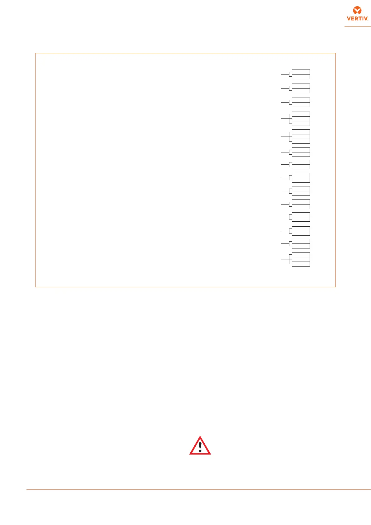
Wiring connections (Fig. 13):
• Connection for remote on-o must be done by the installer.
• The General Alarm terminals allow remote alarm signaling.
• In case of short circuit, check the sticking of the involved
switch and replace it.
6.4 - Protection degree IP2x check
After whole of the connections and installation works, comprising
ceiling elements (plenum, ducting) and oor elements (base frame),
check and verify the protection degree IP2x (protection against nger
access, std. IEC 60364-1) at the boundary of the air conditioner.
6.5 - Protective features of EC fan
The EC fan has been provided with the following protective features:
• Electronics overheating protection
• Motor overheating protection
• Locked rotor protection
• Short circuit at the motor output
With any of these failures, the motor stops (electronically - no
potential separation), the status relay is released.
NO automatic restart. To reset the alarm, power supply has to be
switched o for min. 20 s once motor is at standstill.
• Mains under-voltage detection:
if mains voltage falls below 3ph/290Vac (typical value) for 5s
minimum, motor will be switched o (only by electronics, no
potential separation), status relay is released.
If mains voltage returns to correct values, the motor will
restart automatically.
• Phase failure recognition:
if one phase fails for 5s minimum, motor will be switched o
(only by electronics, no potential separation), status relay is
released.
If all 3 phases return to correct values, the motor will
restart automatically within 10-40s.
The power supply for an external speed setting potentiometer is
short-circuit protected.
Motor is overload-protected via motor current limitation.
Warning! Leakage current of the motor is approx. 7 mA.
Fig. 13 - Available terminals
cloggedlter (CF)
(CLOSE =OK)
remote on-o
(CLOSE =ON)
smokestat restat(AAP)
optional (CLOSE =ON)
(*) water leakage (LWD)
GENERALALARM
(400, 401NC=alarmorunito)
operatingfan
(CLOSE =ON)
operatingcompressor1
(CLOSE =ON)
user alarm 1
(CLOSE =OK)
user alarm 2
(CLOSE =OK)
operatingcompressor2
(CLOSE =ON)
WARNING
(300, 301NC=warning or unit o)
(Cooling +Electr. heating+Humidication)
AUXILIARY TERMINAL BOX
86
83
400 (NC)
401(C)
402(NO)
70
71
72
73
76
77
78
79
86
030
86
82
300 (NC)
301(C)
302 (NC)
74
75
4compressors
394
0394
362
361
710
720
operatingcompressor3
(CLOSE =ON)
operatingcompressor4
(CLOSE =ON)
Note : Connect 70C terminal withLiebert MC Condenser terminal 700, connect 71C terminal withLiebert MC Condenser terminal 710,
connect 230C terminal withLiebert MC Condenser terminal 230.
70CLiebert MC Condenser, common controlsignal
71CLiebert MC Condenser, circuit1controlsignal
230C LiebertMCCondenser, circuit 2control signal
70C
71C
230C