21
Liebert
®
PDX, EconoPhase Version - UM - 265133 - 29.08.2019
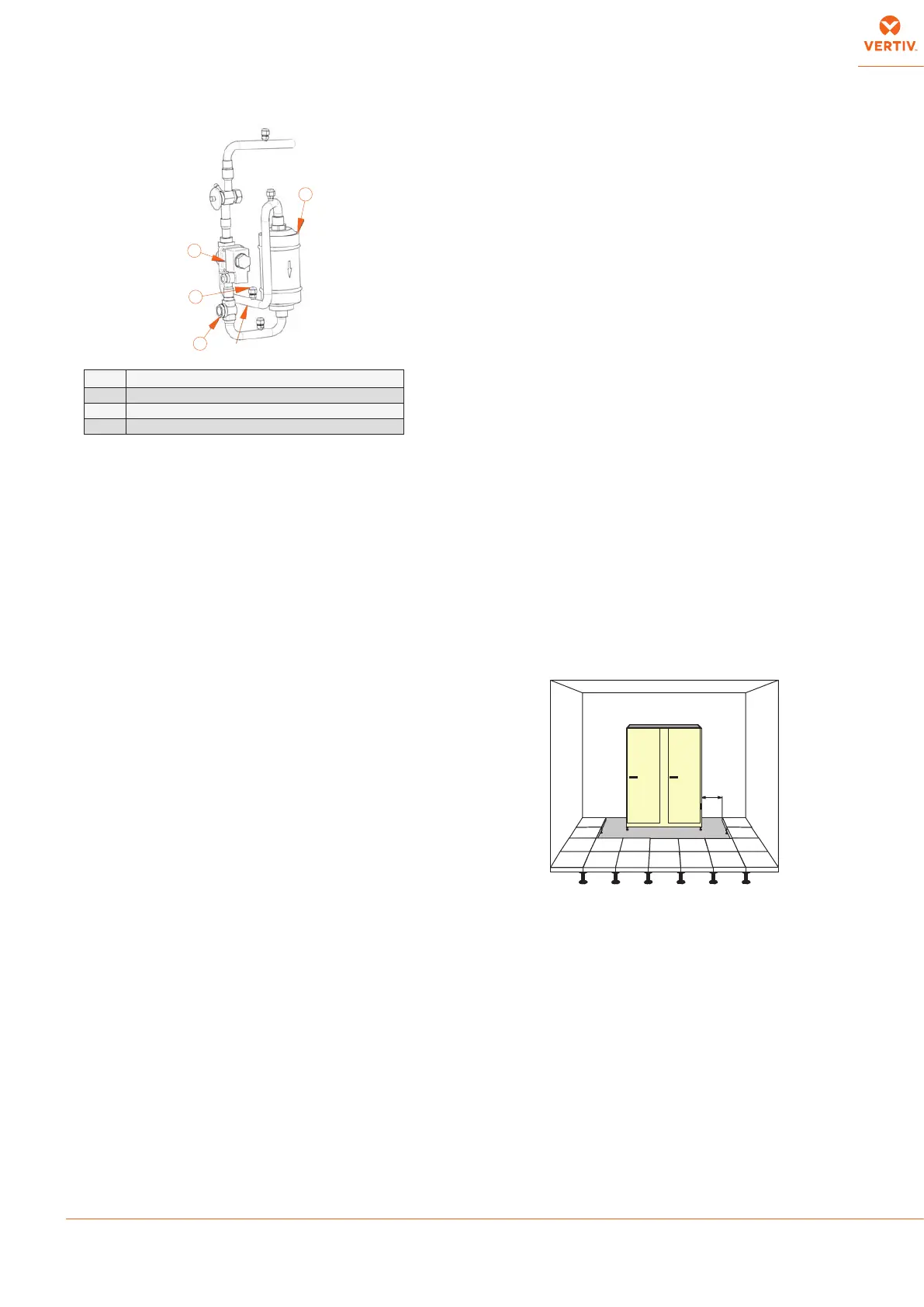
Fig. 14 - Refrigerant line components
8 - Operation
Unit operation is completely automatic. The below sequence
explains how the unit operates :
• The air, sucked in by the fan, enters the unit.
• The air is immediately ltered.
• The TEMPERATURE sensor or HUMITEMP (temperature +
rel. humidity) sensor (check type installed), veries the state of
the inlet air, and relays this information to the control system.
• Filtered new air is injected into the air stream via the Fresh Air
Intake (optional).
• The treated air passes through the fans, which operate
continuously, and is then dispersed out of the unit.
• The air passes from the underoor void into the room via
air distribution outlets. For “DOWNFLOW” units installed on
raised oor: switch o the machine before the oor panels
removal within a distance of 850mm from the machine, to
avoid risks of contact with rotating devices (fans) moving and
with hot heating elements. (see Fig. 15).
• The control system compares the relayed information to the
set point and proportional band values programmed into its
memory: it then commands the air conditioner to treat the air
as follows (see also Control manual):
• COOLING
The compressor (scroll compressor or digital scroll compressor,
with modulating capacity) is started and the cold refrigerant
ows through the evaporator, thus cooling the air passing over
it. For compressor operation see Control manual.
In dual circuit units, the evaporator is a dual stage coil, so the air
is cooled rst by one circuit (circuit n°1, compressor(s) on the
left side) and then by the other one (circuit n°2, compressor(s)
on the right side) . Temperature and pressure values related to
the two refrigerant circuits can be dierent.
• HEATING
This can take one of three forms:
• electrical heating (optional): the heating elements heat
the air passing over them. There is 1 heating step.
• Note: To protect the unit from superheating, one automatic
reset sensor set at 40°C and one or more manual reset
thermostats set at 120°C are installed.
• DUAL POWER SUPPLY - optional
This option allows a supply of electrical power from two
dierent electrical sources. It is possible to chose between
dierent solutions:
• Dual Power Supply Parallel: 2 separate power supplies:
during normal working mode both are present, during
emergency situation only the main one is present.
This means that during emergency mode full cooling
redundancy is granted disabling heating and humidifying.
This last option allows, during emergency mode, to
reduce unit power absorption and therefore Genset or
UPS sizes.
• Dual Power Supply Alternate Basic Version: 2 separate
power supplies: each power supply is able to completely
feed the unit. In case of failure of the main supply the unit
automatically switches to the second power supply. This
allows having a complete power supply redundancy or in
case needed to have during emergency mode full cooling
redundancy disabling heating and humidifying. This last
option allows during emergency mode to reduce unit
power absorption and therefore Genset or UPS sizes.
• DEHUMIDIFICATION - optional
DX mode
Compressor(s) starts and the air ow is reduced, thereby
causing dehumidication (refer also to Control manual).
Note: If, during dehumidication, the ambient temperature
drops below a specied level, dehumidication will be stopped
if necessary (see LOW LIMIT intervention in Control manual).
• HUMIDIFICATION - optional
The humidier creates steam, which is distributed into the air
stream via the steam distribution pipe (see also Enclosure A,
F, G).
Note: Manual control can be performed using the control system
(see Control manual).
Fig. 15 - Safe oor panels removal
9 - Calibrations & Regulation
(at start-up)
The air conditioner has already been factory tested and calibrated,
but it is very important to check, at start-up, the superheating.
See Tab. 5 and Tab. 6 (Enclosure B) that show all valves.
• The air conditioner has already been factory tested and
calibrated.
• For calibrations of instruments installed on the external
condensers/Dry coolers refer to the relevant manual.
• For control system calibrations refer to Control manual (to
prevent erratic operations do not use temperature sand rel.
humidity set points/proportional bands which dier excessively
from the Standard Settings).
1 Filter dryer inlet Schrader valve
2 Filter dryer
3 Sight glass
4 Solenoid valve (only with thermostatic expansion valve)
from Liquid
Receiver
4
1
2
3
850 mm
1 Filter dryer inlet Schrader valve
2 Filter dryer
3 Sight glass
4 Solenoid valve (only with thermostatic valve)