Enclosure B - Technical data table
B - 1 Liebert
®
PDX, EconoPhase Version - UM - 265133 - 29.08.2019
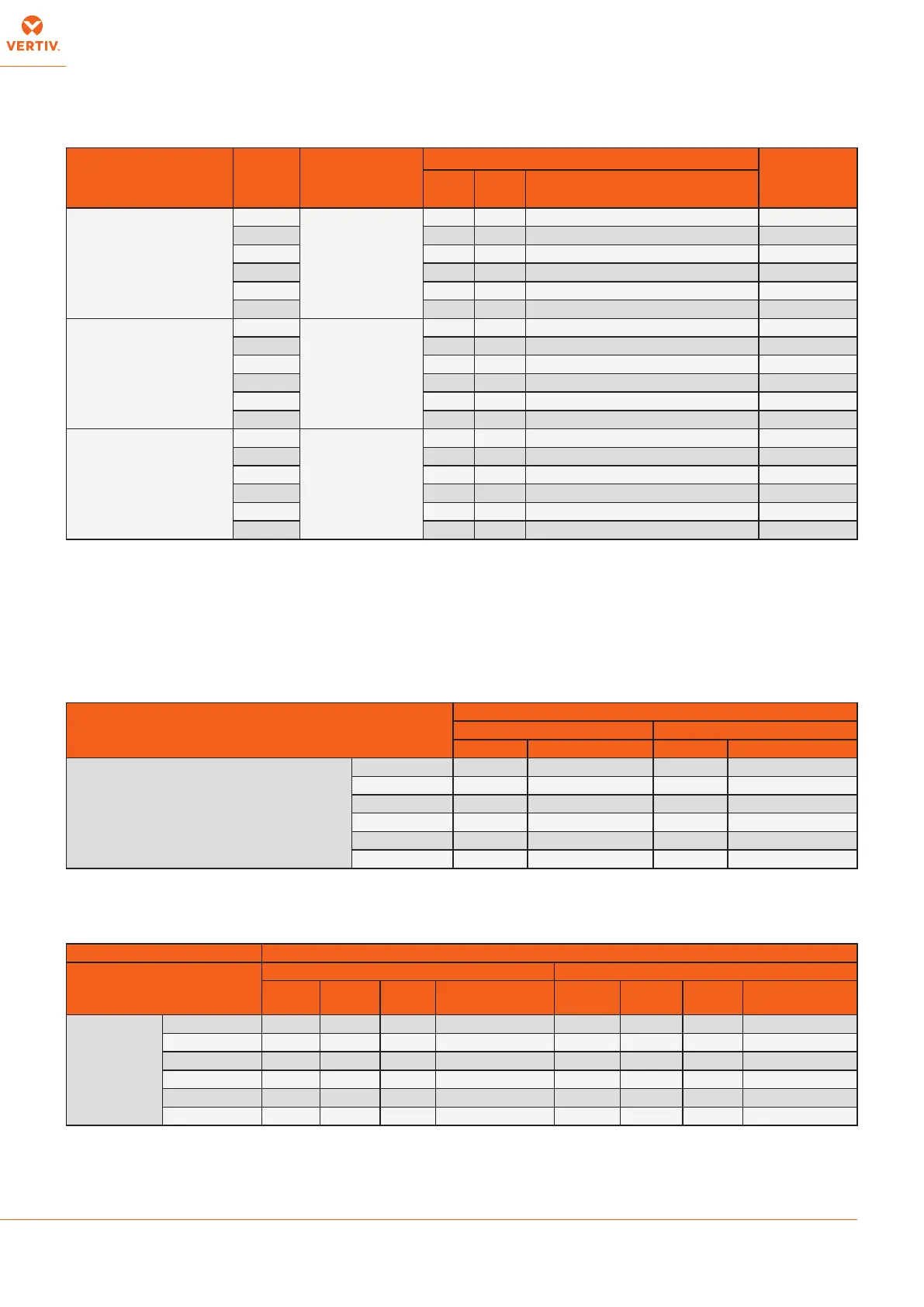
Tab. 1 - Electrical data with premium fan module
* ATTENTION Only universal (type B, B+) RCD protective devices are permitted.
NOTES:
• The cables have to be sized in compliance with local standards and according to the type and characteristics (e.g. Amperes) of installation.
• The data in the tables do not consider the absorbed current from the condensate pump and for other options not explicitly described.
• The specic energy allowed to ow from the circuit breakers, installed by the user, must be lower than 300.000A
2
x s.
• Prescriptions on the dierential relay required to the user:
• for special places (healthcare facilities, etc...) comply with the local regulations;
• For ordinary places, a low sensitivity is suggested (300 mA) coordinated with the value of the ground heater (IEC 364): Ra 50/Ia (Art. 413.1.4.1, CEI 648 or IEC60364445);
• In case of frequent over-voltages with mains impulse, it is advisable to install a selective dierential and to evaluate the need for adopting other devices;
• The FLA is for units without the options of condensate pump and condensing unit;
• The FLA is for units with AUTOMATIC FUNCTIONS only: in manual mode operation the FLA must be lower than the max. current of the main switch.
Conguration Model Power supply
DIGITAL SCROLL Cooling System
min./max. Cu
cable size
FLA
[A]
LRA
[A]
Residual- Current Circuit Breakers
Inn = 0.3A (400V)*
Cooling Fan(s) +
Compressor(s)
PX082
400 V /
3 Ph + N /
50 Hz
+ earth
73 148 100A “C” 10..70mm
2
PX094 73 174 100A “C” 10..70mm
2
PX104 77 172 100 A “C” 10..70mm
2
PX120 101 219 125 A “C” 10..70mm
2
PX150 142 250 160 A “C” 10..70mm
2
PX165 160 300 200 A “C” 10..70mm
2
Cooling + Electrical
heaters (Dehumidication)
Fan(s) + Compressor(s)
+ Electrical heaters
PX082
400 V /
3 Ph + N /
50 Hz
+ earth
76 148 100A “C” 10..70mm
2
PX094 76 174 100A “C” 10..70mm
2
PX104 78 172 100A “C” 10..70mm
2
PX120 101 219 125A “C” 10..70mm
2
PX150 174 283 200A “C” 10..70mm
2
PX165 192 332 200A “C” 10..70mm
2
Cooling + Electrical
heating + Humidication
Fan(s) + Compressor(s)
+ electrode or infrared
humidier
PX082
400 V /
3 Ph + N /
50 Hz
+ earth
87 148 100A “C” 10..70mm
2
PX094 87 174 100A “C” 10..70mm
2
PX104 91 172 125A “C” 10..70mm
2
PX120 115 219 125A “C” 10..70mm
2
PX150 156 264 160 A “C” 10..70mm
2
PX165 173 313 200 A “C” 10..70mm
2
Tab. 2 - EC fan connections
NOTE:
The EC fan settings can be modied acting on the control display (see Control manual).
(*) Setting for Nominal Airow at standard conditions, Filters class F5, ESP: Downow Up 20 Pa; Downow Frontal 0 Pa.
Model
EC Fan signal [VDC]*
Downow Up Downow Down
STD Dehumidication STD Dehumidication
version with premium fan module
PX082 A 8,3 7,3 8 7
PX094 A 9 8 8,6 7,6
PX104 A 9,4 8,4 8,9 7,9
PX120 A 9,4 8,4 8,9 7,9
PX150 A 7,9 6,9 7,5 6,5
PX165 A 9,6 8,6 8,9 7,9
Tab. 3 - Electrical data (standard components)
Component EC Fan (400V / 3Ph / 50Hz)
Model
Downow Up Downow Down
OA* [A] FLA [A]
LRA
[A]
Nominal power*
[kW]
OA* [A] FLA [A] LRA [A]
Nominal power*
[kW]
version with
premium fan
module
PX082 A 3x2.63 3x5 3x0.1 3x1.73 3x2.35 3x5 3x0.1 3x1.54
PX094 A 3x3.21 3x5 3x0.1 3x2.13 3x2.87 3x5 3x0.1 3x1.9
PX104 A 3x3.54 3x5 3x0.1 3x2.35 3x3.16 3x5 3x0.1 3x2.1
PX120 A 3x3.55 3x5 3x0.1 3x2.36 3x3.16 3x5 3x0.1 3x2.1
PX150 A 4x3,18 4x7,4 4x0,1 4x2,06 4x2,82 4x7,4 4x0,1 4x1,81
PX165 A 4x5,72 4x7,4 4x0,1 4x3,76 4x4,66 4x7,4 4x0,1 4x3,09
(*) At standard operating conditions, Filters class F5, ESP: Downow Up 20 Pa; Downow Frontal 0 Pa.
(**)At nominal operating conditions: Condensing temperature 45
0
C - Room conditions 24 C / 50% RH