Vertiv | Liebert PEX4 | User Manual 21
Installation
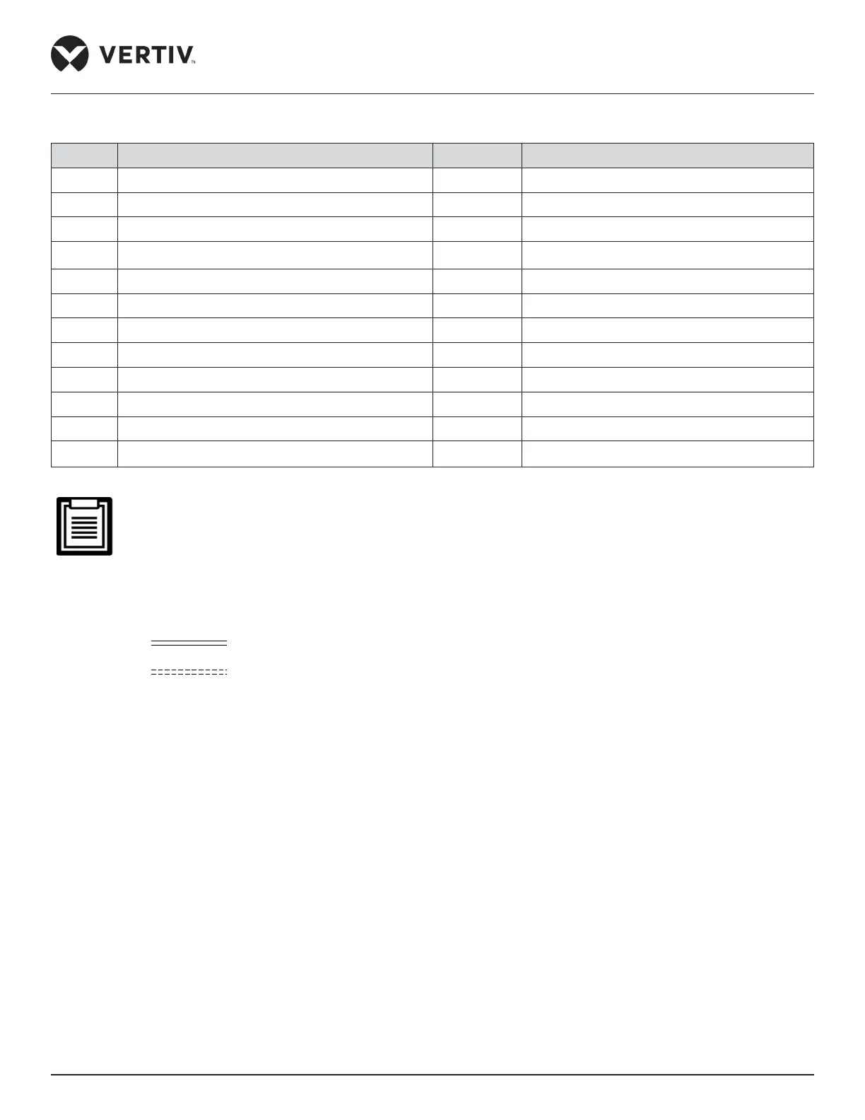
List of the components of system arrangement diagram (Figure 2-8) is given in the below table.
No. Description No. Description
1 EC/ AC fan 13 LP transducer
2
+
Check valve 14 Suction temperature sensor
3 Condenser Coil 15 Evaporator coil
4*
Oil trap (mounted one at every rise of 7.5 m) 16 EC fan
5 Shuto valve 17 Schradar valve
6 Discharge temperature sensor 18 Electronic Expansion Valve
7 Discharge line 19
+
Solenoid Valve
8 HP transducer 20 Sight glass
9 HP switch 21 Filter dryer
10 Scroll Compressor 22 Schradar valve
11 Schradar Valve 23 Shuto valve
12 Suction line 24 Refrigerant ow
The following points should be considered before checking out the overall layout diagram:
• The single system is used as an example.
• Components (marked with *) are not supplied by Vertiv but are recommended for the proper circuit
operation and maintenance.
• +: When the pipeline equivalent length exceeds 30 m, these components are optional.
• : Factory piping
• : Field piping (by technical personnel)

 Loading...


