Vertiv | Liebert PEX4 | User Manual 22
Installation
2.2.6. System Installation Mode
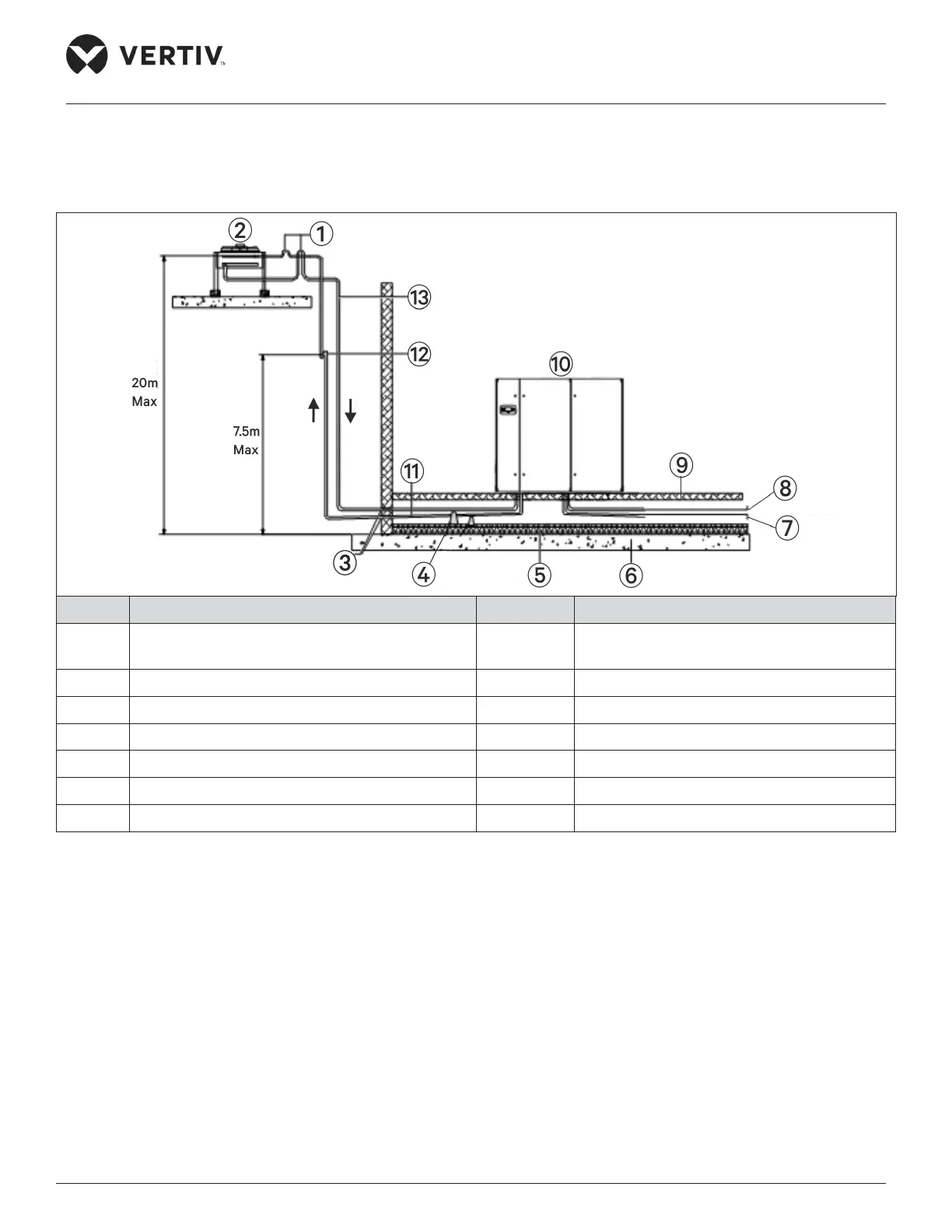
The system installation schematic diagram explains the process of installation for the condenser.
No. Description No. Description
1 Inverted traps (higher than the highest copper
pipe of condenser)
8 Humidier supply pipe
2 Outdoor unit 9 Raised oor
3 Sealed 10 Indoor unit
4 Supporting bars 11 Discharge pipe slope
5 Thermal isolated layer under oor 12 Oil trap (Oil storage bend)
6 Floor 13 Liquid pipe (avoid direct sunlight)
7 Condensate drain pipe
Figure 2-9 Condenser is Placed Higher than the Compressors during Installation
If the condenser is installed higher than the compressor (see Figure 2-9), a back-bend should be tted to the
discharge line and liquid line of the condenser, so as to prevent the liquid refrigerant from owing back when
the condenser stops. The top end of the inverted back-bend should be installed higher than the ultimate level
of the copper pipe of the condenser. However, if the condenser is installed lower than the compressor, then
there is no need of modication.
 Loading...


