Vertiv | Liebert PEX4 | User Manual 50
Installation
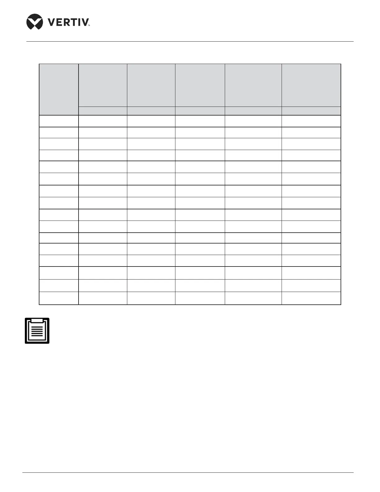
Table 2-16 Rated Full Load Ampere (FLA) (unit: A)
Models
Full Load amps
(Comp+ Fan)
Col. A
+
1 Stage
Heating
Col. A
+
2 Stage
Heating
Col. A
+
Electrode
Humidication
(No Heating)
Col. A
+
Infrared
Humidication
(No Heating)
(A) (B) (C) (D) (E)
P1035 (U/D) 27.4 41.0 54.6 32.6 33.6
P1045 (U/D) 29.5 43.1 56.7 34.6 35.6
P1050 (U/D) 37.8 51.4 65.0 43.0 43.9
P1060 (U/D) 38.7 52.3 65.9 43.8 44.8
P2070U 54.9 73.0 91.2 63.2 64.1
P2080U 58.9 77.1 95.2 67.2 68.1
P2090U 58.9 77.1 95.2 67.2 68.1
P2100U 75.7 93.8 111.9 83.9 84.8
P2110U 75.7 93.8 111.9 83.9 84.8
P2120U 77.4 95.5 113.6 85.6 86.5
P2070D 54.9 73.0 91.2 63.2 66.3
P2080D 58.9 77.1 95.2 67.2 70.4
P2090D 58.9 77.1 95.2 67.2 70.4
P2100D 75.7 93.8 111.9 83.9 87.1
P2110D 75.7 93.8 111.9 83.9 87.1
P2120D 77.4 95.5 113.6 85.6 88.8
• FLA values of rst four single compressor-based models are same for Upow (U) and Downow (D) units.
• The FLA values of Air-cooled unit do not account the outdoor unit current.
• MCB & Cable sizes are selected as per local electrical norms.
2.8.3. Connecting Control Cables
The position of eld connection terminals is shown in Figure 2-31 and the enlarged view of the terminal
optimizing aisle is shown in Figure 2-32. The upper part of the terminal optimizing aisle is connected with the
unit, and the lower part is the interface of the user control signal line.
 Loading...


