Vertiv | SmartAisle2 | User Manual 109
Installation
• Use the straight-through cable connection between the sensor and monitoring unit RDU-A G2.
• Requires a series of adjacent sensor network cable, network cable should be preferably black. Use the cor-
rect network cable tester to check the cable line sequence.
• The temperature and humidity sensors are set to address TH1, 2, 3, 11, 21, 31; TH4 4,5,6 address are set to 12,
22, the address is set to 4DIF sensor 10. The address setting mode can be found by referring to the intelli-
gent temperature and humidity sensor manual, and IRM-S04D1 Phoenix smart digital sensor interface input
user manual.
• 4DI is set to the user mode meaning the sensor 6 bit DIP switch is ON.
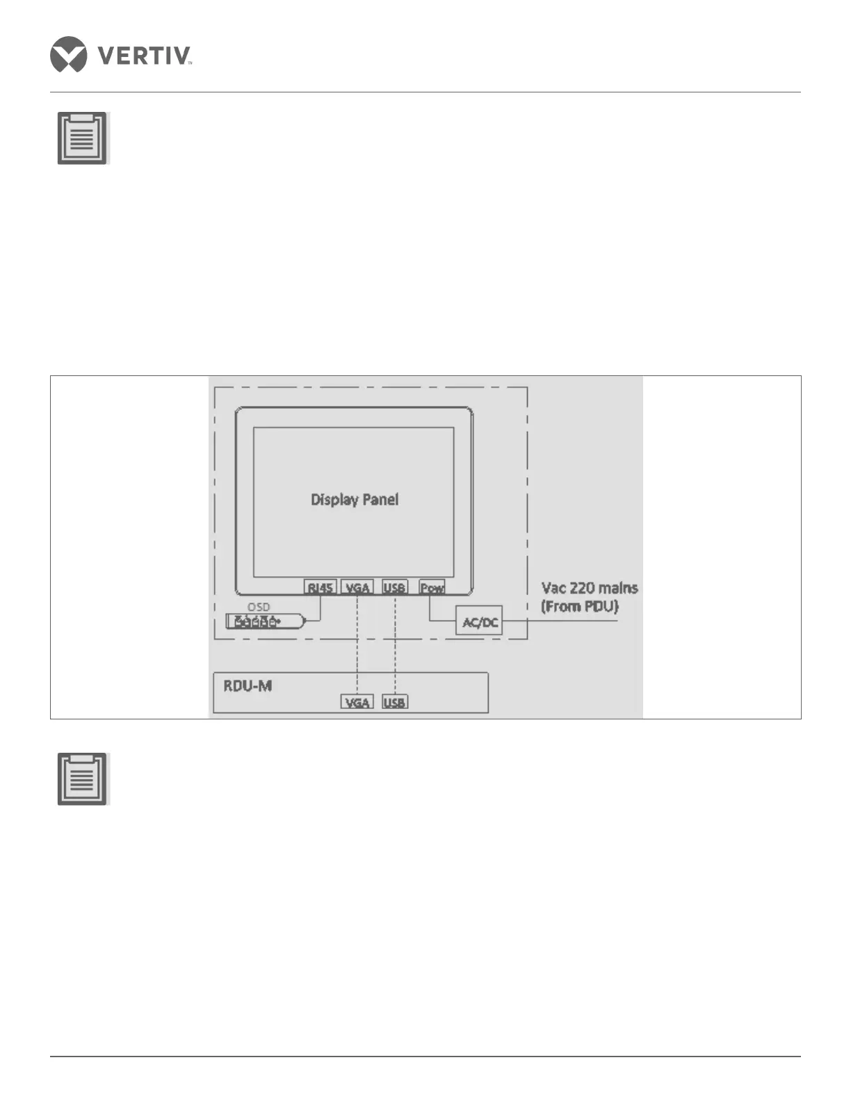
Control Panel
Figure 2-125 Control Panel
• Tighten the VGA cable to prevent loosening
 Loading...


