Vertiv | SmartAisle2 | User Manual 102
Installation
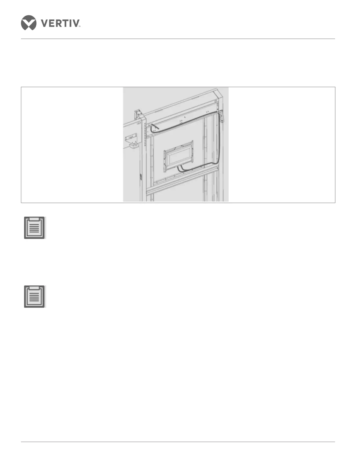
Wiring the Control panel
The wiring control panel is shown in Figure 2-113.
Figure 2-113 Wiring of the control panel
• When the terminal box covers the door near the door of the cartridge frame post completion of adjustment
of the cable length and cable binding, the door cover sheet cartridge frame is hanging on the door.
• The cover plate to the door frame between the door pockets across the cable section helps reserve a
certain length to prevent the cable-operated door being subjected to extreme stress when the cover is
removed.
2.13.8. Install the sensor
• For detailed installation instructions on the respective sensors, refer to the IRM-S02TH intelligent tem-
perature and humidity sensor user manual, IRM-S011N Phoenix smart digital sensor interface input user
manual, IRM-S01W-belt type water sensor user manual, the IRM-S011N infrared sensors user manual,
ES-HND200-E1 definition hemispherical camera installation manual, and the JTY-GD-S832 photo-electric
smoke type fire detector user manual.
Mounted Temperature and Humidity Sensors
• IRM-S02TH temperature and humidity sensor is installed in the upper portion of the magnet channel region
within the closed cabinet door frame assembly as shown in Figure 2-114.
• 6 Nos. of standard temperature and humidity sensors are fitted uniformly on both sides of the inner channel in
the cabinet. This is to ensure the accuracy of measurement of the temperature and humidity throughout the
enclosed channel.