EasyManuals Logo

Vertiv Liebert SmartAisle2 User Manual

Vertiv Liebert SmartAisle2
141 pages
To Next Page IconTo Next Page
To Previous Page IconTo Previous Page
Page #12 background imageLoading...
Page #12 background image
Vertiv | SmartAisle2 | User Manual 3
Introduction
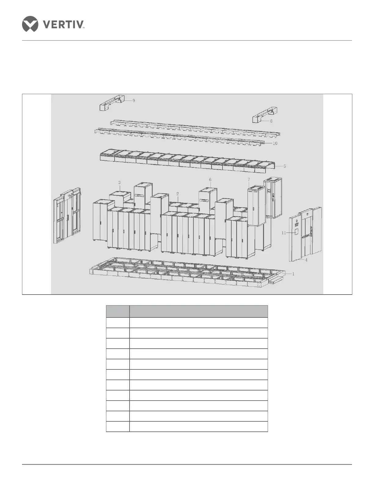
1.3. Appearance and Components
The bifurcation of all components that constitute the SmartAisle2 solution is depicted in Figure 1-1.
Figure 1-1 SmartAisle2 layout diagram
Sl. No. Details of Equipment
1 Base
2 Server Cabinet
3 Network Cabinet
4 Access door
5 Top Plate
6 A/C Column
7 Distribution Cabinet
8 Strong wire passage groove
9 Power cable trunking; copper and fiber cable tray
10 Cabinet top wire groove
11 Control panel

Table of Contents

Questions and Answers:

Question and Answer IconNeed help?

Do you have a question about the Vertiv Liebert SmartAisle2 and is the answer not in the manual?

Vertiv Liebert SmartAisle2 Specifications

General IconGeneral
BrandVertiv
ModelLiebert SmartAisle2
CategoryControl Unit
LanguageEnglish

Related product manuals