Vertiv | SmartAisle2 | User Manual 57
Installation
• Control wire is connected to:
» Connect the motor unit connector securely. The terminal station device must be securely mounted and
properly connected to the control device with a fixed wire line card.
» Securely install the power switch so that it is firmly connected to the control unit.
» Use the supplied line card to secure the wire.
» Fixed control device.
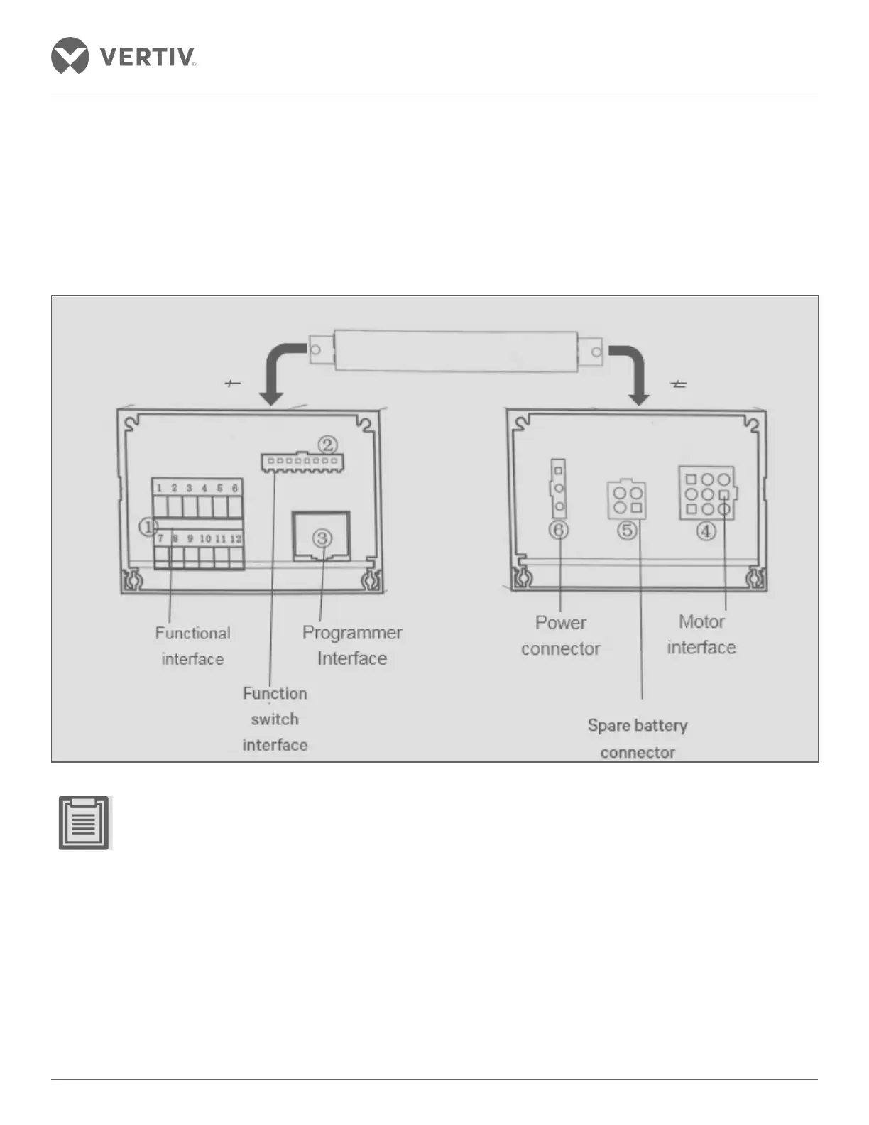
Figure 2-53 Schematic diagram of an interface control device
• Lead wire from above through the motor device.
• Careless connections in the above locations can lead to malfunction.
• When connecting, the control device needs to be loosened to adjust the position. After the connection is
completed, attention should be paid to fixing the control device.
• F is set to stop the pendulum adjusted.
» Loosen the adapter nut in the F position and adjust the position of the F position before and after, so that
the front and rear positions of the glass door are centered, and there is no obvious friction between the top
and the top of the column. After the adjustment, tighten the nut.