030624.13 19
vetus® Electronic engine remote control
Trim/Flap
Trolling
Trim/Flap
Trolling
Throttle
Throttle
Fuse
Canbus
+12 V
+24 V
Gear
Neutral switch
Gear
Neutral switch
Left engine Right engine
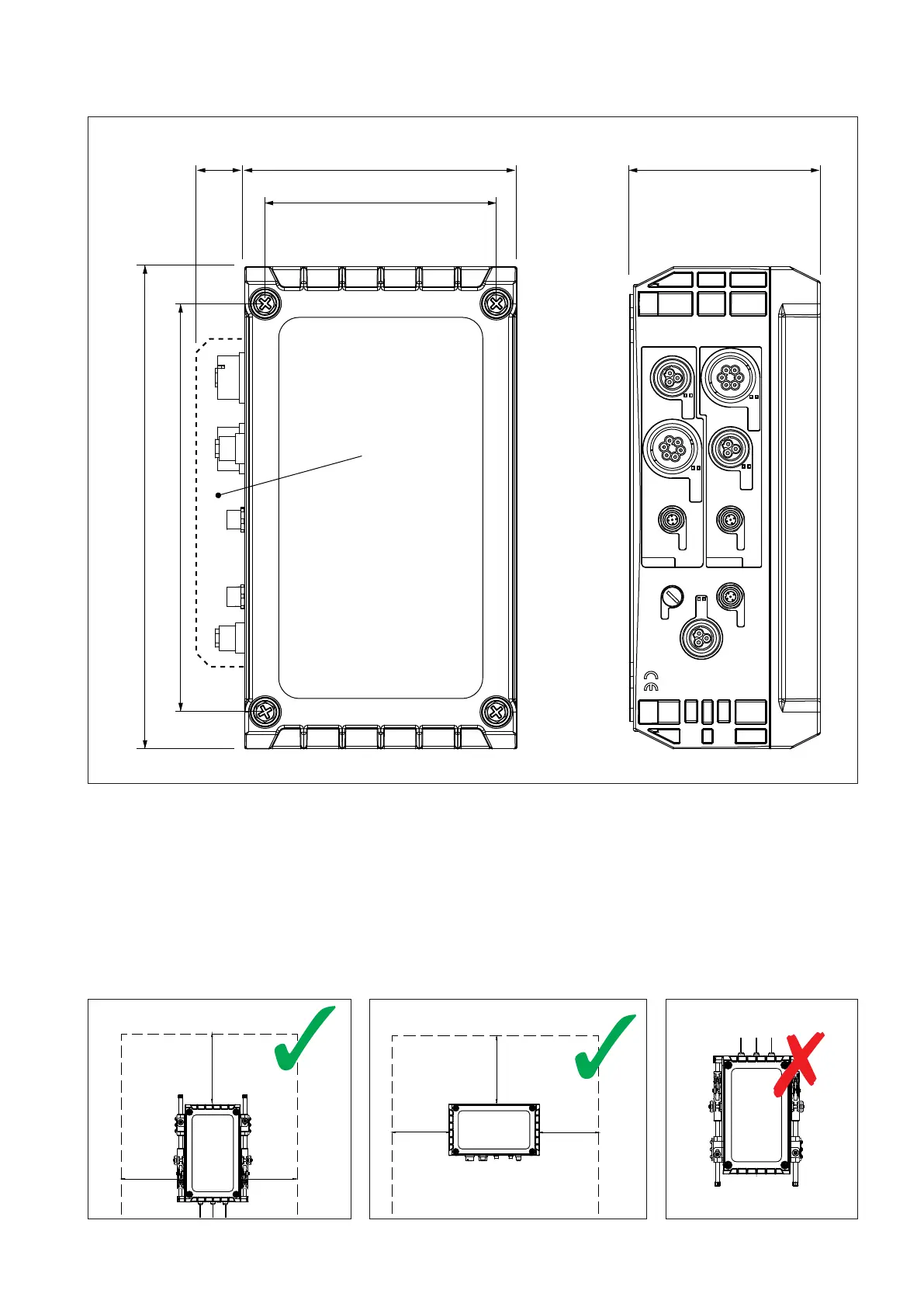
142 (5
9
/
16
”)200 (7
7
/
8
”)
170 (6
11
/
16
”)
35 (1
3
/
8
”)
354 (13
15
/
16
”)
300 (11
13
/
16
”)
Connectors area
5.2 Drawing of full electronic actuator
Mount the actuator leaving a space of at least 25 cm on each side
Do not install the actuator
with the connectors upwards
A > 25cm (10”)
A
A
A
A > 25cm (10”)
A
A
A
5.3 How to mount the Actuator
The actuator must be mounted in the engine room in a safety place and as near as possible to the propulsion engine. The
actuator cannot be exposed directly to the source of vibrations, e.g. it cannot be mounted directly on the engine, on the
gearbox or on the engine base.