24 030624.13
vetus® Electronic engine remote control
6 Accessories and Options
Cables reported here below are used in standard instal-
lations. For specific engines there are anyhow available
cables with their proper connectors; in case you need
cables for specific engines, please contact the supplier.
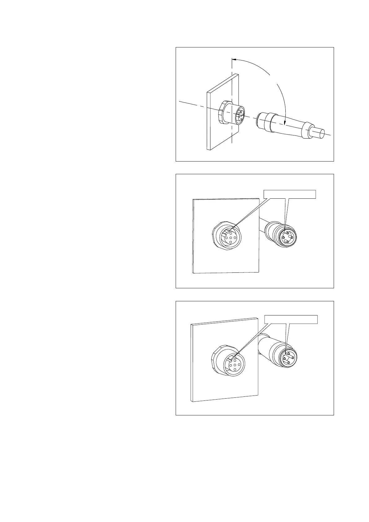
For a correct mounting plug in the connector at 90°
with respect to wall side of the actuator box. Rotate
then the ring until the cable enters into the counter-
part M12.
If the cable has been inserted correctly, it must be pos-
sible to screw completely by hand the cable without
too much efforts. The best electrical connection and the
max water protection of this connector is reached when
screwed with around six turns.
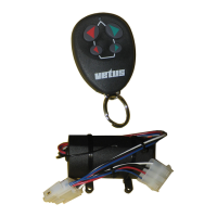
Connector for throttle cables
Engine cables must be installed as far as possible from
heat generating sources. If the cable is running for
some of its length nearby the engine, protect this part
of the cable with a cover suitable to reflect the heat
generated by the engine.
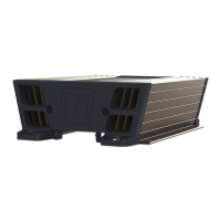
Connector for CANbus data transmission cable
90°
Cable connector
Polarization code B
Wall connector
Cable connector
Polarization code A
Wall connector