28
EN
16657715_en 05/2006
ab
4.6 Setting pick-up
4.6.1 Setting pick-up height
The pick-up is raised and lowered hydraulically using
the tractor control unit.
The pick-up height is adjustable unsing the two gauge
wheels.
The height at which material is lifted up cleanly is to be
set in accordance with the ground conditions and the
quality of the baling material.
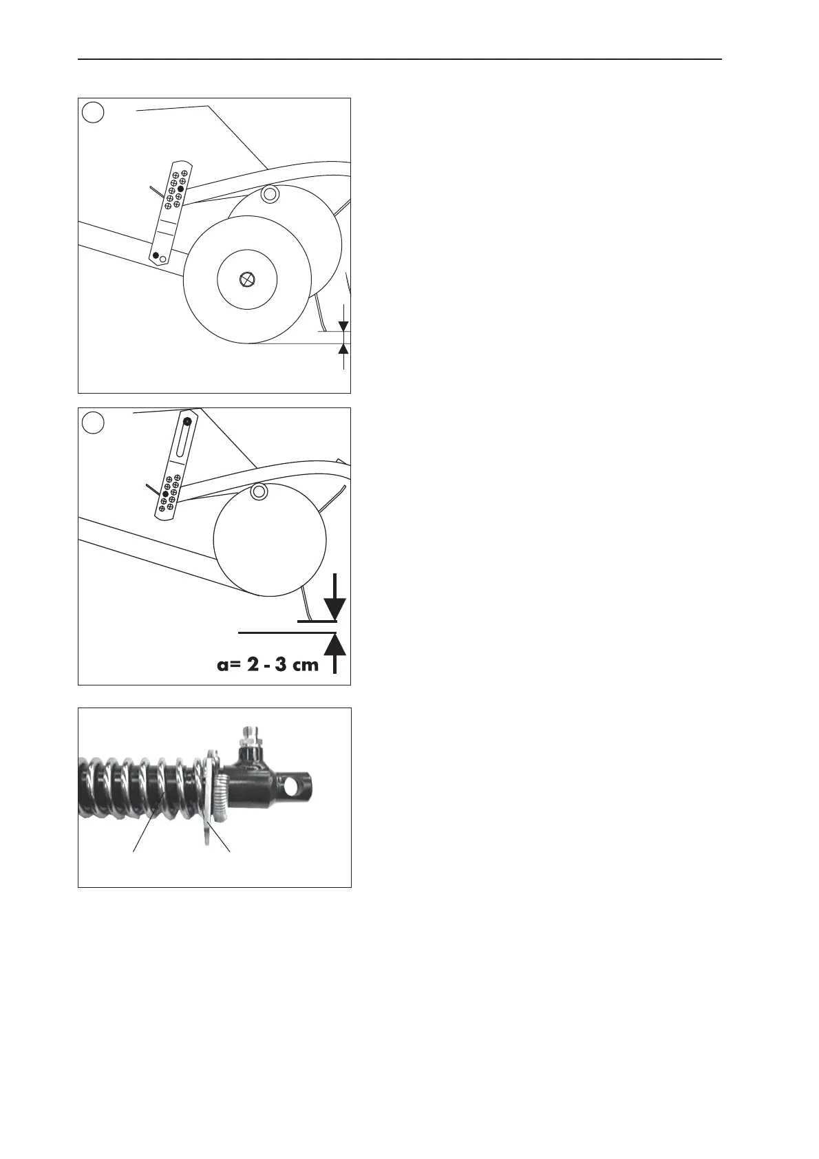
The distance between the tine tips at their lowest position
and the ground is the decisive factor. A standard value
of a = 2-3 cm can be taken for this distance. The tines
should not come into contact with the ground to prevent
the baling material becoming dirty and above-average
wear of the tines.
The distance from the tine tips to the ground can be
adjusted using the 2x6 holes of the gauge wheel control
arm (125 fig. 1) or the 2x6 holes of the perforated
strip (121, fig. 2)
Ensure that the setting at the right and left feeler wheels
is the same.
4.6.2 Setting pick-up unload
The ground pressure of the pick-up above the feeler
wheels can be set using the right and left compensation
spring (a). The springs are pushed by the hydraulic
cylinder of the pick-up lift. Unload can be preset by
selectively inserting the sliding clips (b) into one of the
four positions.
Stronger unloading (foremost groove in direction of
travel) for soft ground or gentler unloading (furthest
groove back in direction of travel) for hard ground and
‘jump’ for pick-up when the ground is not level.
To insert the sliding clips into different grooves, the pick-
up must be raised to the limit.
a = 2-3 cm
1
2
125
121


 To Next Page