24
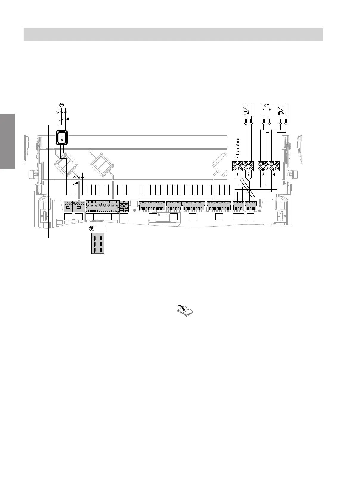
Layout of the electrical connections
Note
For further information on the connections, see the fol-
lowing chapters.
100
209640 35 54 X7 X6 X2 X9 X12 X5
N 1 LNL N L L N N L N L N L
B
L N
A C D E
X20
21
10 987654321 654321 65432178 654321789
Fig. 14
Connections to 230 V~ plugs
A
Power supply
fÖ
B
Configurable floating input
lH
, 230 V
230 V output
230 V room thermostat connection
sÖ
Heating circuit pump
a-Ö
Fan motor
dG
Gas solenoid valve
gF
Ignition unit/ionisation
sA
No function assigned
C
Cylinder temperature sensor (system boiler)
D
Remote control (OpenTherm device)
E
Outside temperature sensor
X
sÖ
Equipotential bonding (earth conductor)
Note on connecting accessories
When connecting accessories observe the sep-
arate installation instructions provided with
them.
Installation sequence
Electrical connections (cont.)
6167586
Installation