47
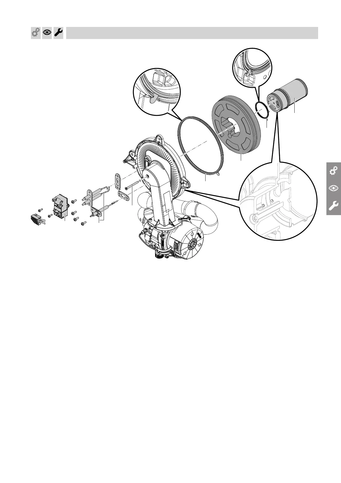
Fig. 31
Check burner gauze assembly D
, electrodes
B
, ther-
mal insulation ring
F
and gasket
G
for damage. Only
remove and replace components if they are damaged
or worn.
Note
If replacing the burner gauze assembly, also replace
the gauze assembly gasket and the fixing screw.
1. Disconnect plug with ignition electrode leads from
ignition unit
A
.
2.
Remove electrodes
B
.
3.
Undo Torx screw
C
. Hold onto burner gauze
assembly
D
when undoing the screw.
4.
Remove burner gauze assembly
D
with gasket
E
and thermal insulation ring
F
. Check components
for damage.
5.
Install new burner gasket
G
. Observe correct
installation position. Align the tab as per the dia-
gram.
6.
Insert thermal insulation ring
F
and burner gauze
assembly
D
with gasket
E
. Observe correct
installation position. Align the tab as per the dia-
gram.
7.
Align the hole in burner gauze assembly
D
with
the burner door pin.
Secure burner gauze assembly
D
and gasket
E
with Torx screw
C
.
Tighten screws as tightly as necessary and ensure
that the components are undamaged and are func-
tioning correctly throughout service life.
Observe torque settings if a torque wrench is avail-
able.
Torque: 3.0 Nm.
8.
Check thermal insulation ring
F
for firm seating.
9.
Fit electrodes
B
. Check clearances, see following
chapter.
Tighten screws as tightly as necessary and ensure
that the components are undamaged and are func-
tioning correctly throughout service life.
Observe torque settings if a torque wrench is avail-
able.
Torque: 4.5 Nm.
Commissioning, inspection, maintenance
Checking the burner gasket and burner gauze assembly
6167586