99
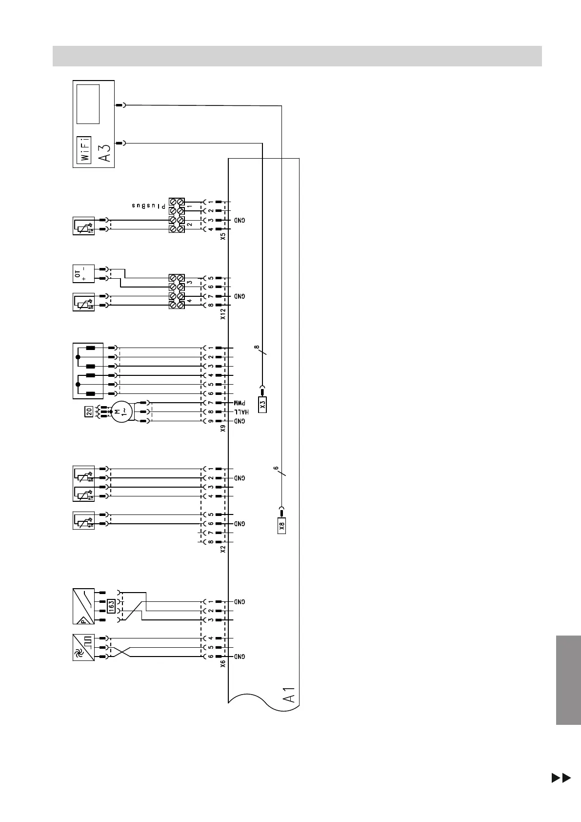
Fig. 62
A1 HBMU heat management unit
A3 Programming unit with communication module
X... Electrical interfaces
G
Flow sensor (combi boiler only)
H
Water pressure sensor
K
Flue gas temperature sensor
L
Boiler water temperature sensor
M
Circulation pump (PWM)
Connection and wiring diagram
(cont.)
6167586
Appendix