QE20 Fibre Networking User Manual Document: LT0732
Page 3-18 24 May 2023 Issue 1.0
• Log in with the default username admin and password admin.
• Click on Network Setup in the heading line and then on these pages (page
names on LHS) enter the settings shown in the order of the table below.
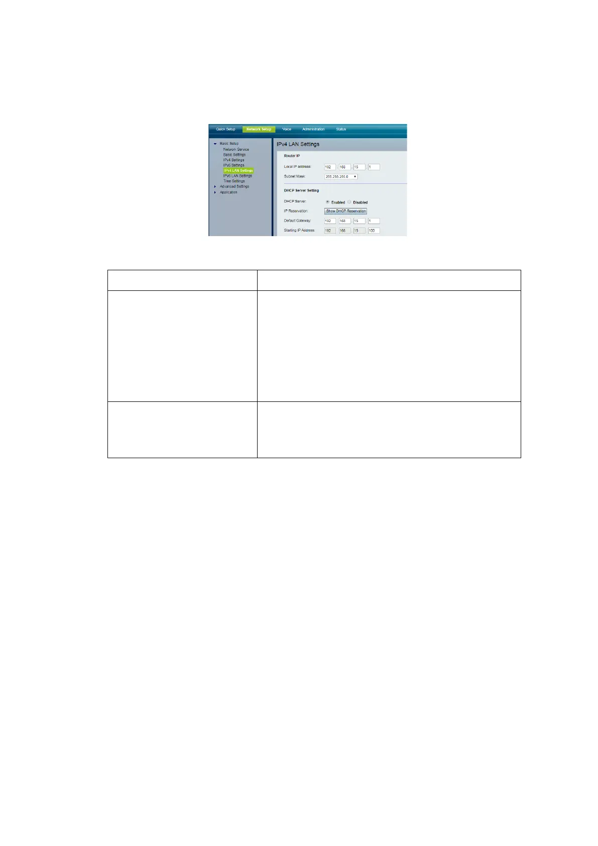
Screen Sample – ATA Network Setup page
Basic Setup | IPv4
Settings
Connection Type : Static IP
Internet IP Address : enter the assigned IP
address (e.g. 10.0.8.1)
Subnet Mask : 255.0.0.0
Default Gateway : 10.0.10.1
Click Submit.
Basic Setup | Network
Service
Click Submit.
The host PC will lose connectivity to the ATA as the ATA’s IP address will
change. Wait until the POWER LED on the ATA is on steady.
Further configuration of the ATA can be done using the built-in Web Server.
3.1.14 Configure ATA Using Built-In Web Server
On a working network:
• Enable the DHCP Server function on the PIB by fitting J13 DHCP
Server/TAMPER. At most one device (PIB, Moxa switch, ATA) on the QE20
network should have the DHCP Server function enabled.
• Using an RJ45 cable connect the PC’s Ethernet port to a spare port on a
Moxa Switch on the network, with the ATA connected to the Moxa switch or
network ring with the PIB.
• On the host PC, open a web browser and browse to the ATA’s web server.
E.g., type ‘http://10.0.8.1’ (use the correct IP address for the ATA) into the
address box of the browser and press Enter. The ATA log in web page
should open.