Document: LT0732 QE20 Fibre Networking User Manual
Issue 1.0 24 May 2023 Page 3-9
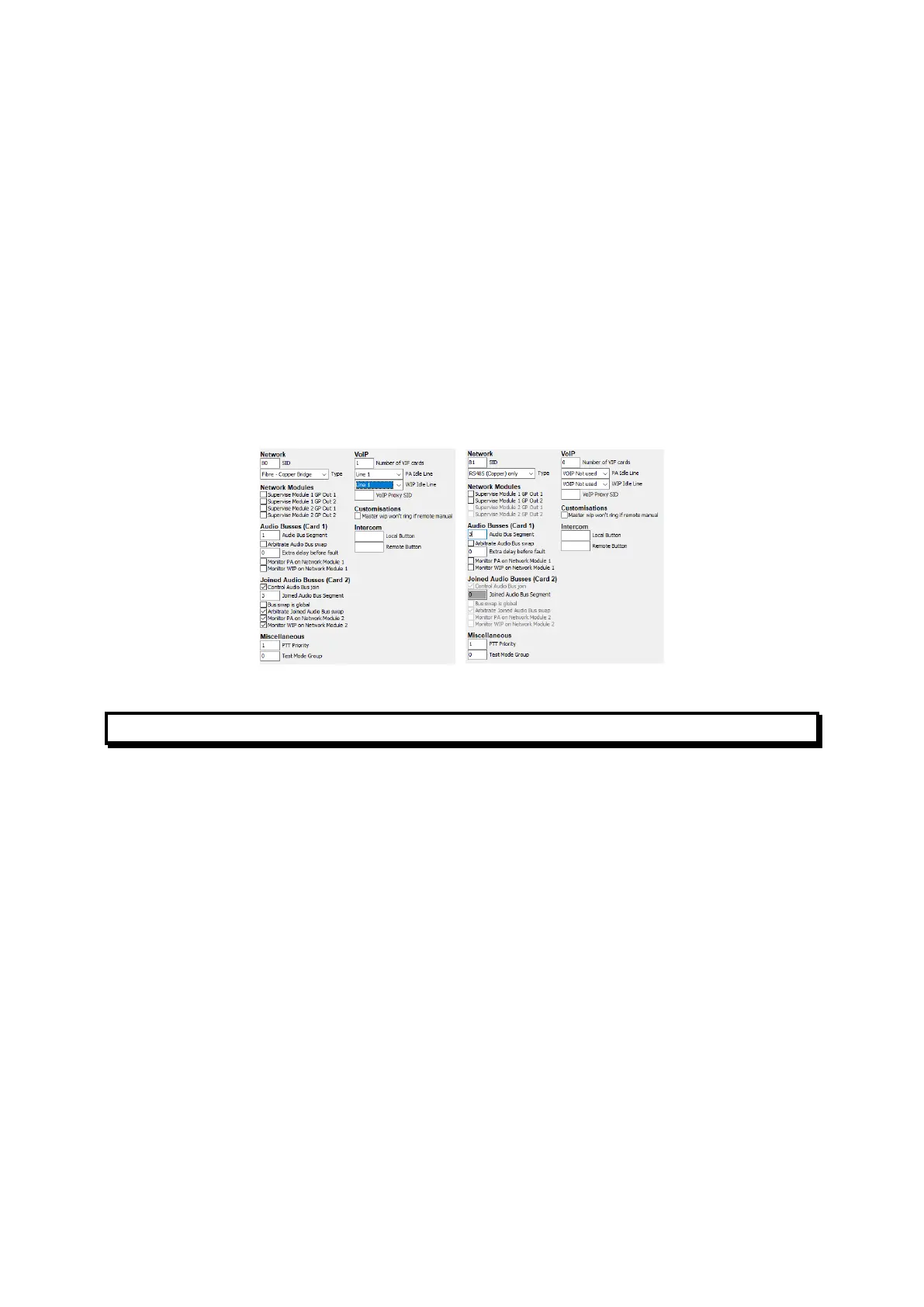
network on their behalf. These panels need to have the SID number of the
Fibre-Copper Bridge programmed into their “VoIP Proxy SID” field on the
Network Page (note: VoIP Proxy in this context does not refer to the
functionality present within the PIB). Additionally, the “Number of VIF Cards”
must be set to 0, and “PA Idle Line” and “WIP Idle Line” must be set to “VoIP
not used”.
• At all panels, the “dial numbers” entered in the Remote SIDs table for SIDs on
copper segments must be the dial numbers required to reach the Fibre-
Copper Bridge for that copper segment.
• Each copper segment needs to be given a unique Audio Bus Segment
(number) so that the audio segments needed to reach QE20 panels on each
copper segment can be identified. For example, SID 80 is the Fibre Copper
Bridge, the main fibre ring is Audio Bus Segment 1, and it provides a RS485 +
audio copper network – Audio Segment 3. SID 81 is connected to SID 80 by
copper cables, so is assigned the matching Audio Bus Segment number.
Figure 6 – Network Configs for QE20 Fibre-Copper Bridge and Copper-Connected QE20
Dial Plans
3.1.10 ATA Dial Plans
The ATA must be configured to translate the phone numbers dialled by the QE20
and VIF into IP addresses and destination ports. This could be done using a “Dial
Plan” that:
• allows a single digit to be dialled and maps this to a “speed dial” for each
required digit (not recommended as it is slow), or
• generates an IP address with part of the IP address incorporating the dialled
number (recommended).
Some examples are given here in sufficient detail to allow them to be amended for
particular networks, but a full description of ATA dial plans is beyond the scope of
this manual. For more information refer to the specific ATA Administration Guide.
3.1.11 Using a Dial Plan to Generate an IP Address from a Phone
Number
For information on creating dial plans refer to the specific ATA Administration Guide.
The methods in these examples use <input:output> blocks in the dial plan, where
input represents the number dialled, and output represents the resulting digits
forming the IP address:Port number.
 Loading...

