QE20 Fibre Networking User Manual Document: LT0732
Page 3-8 24 May 2023 Issue 1.0
3.1.6 Configuration of VoIP Dial Numbers
In QE20Config the QE20 must be configured with the phone numbers for each
remote node that must be reached by VoIP. This 2-digit number is “dialled” by the
VIF module whenever it is required to set up a VoIP call to the remote node.
Separate numbers can be entered for Speech, WIP 1:1 calls, and WIP All-Call. The
same number may be used for Speech (PA) and WIP - however, in the ATA
configuration, PA lines can be set up to call only PA lines and WIP lines are set up to
call only WIP lines, by using for example line 1 at port 5060 for PA and line 2 at port
5061 for WIP.
When WIP All-Call is to be received from another QE20, a different number - that of
the WIP VoIP PIB proxy – needs to be dialled. Use the “VoIP WIP All-Call Dial
Number” for this purpose.
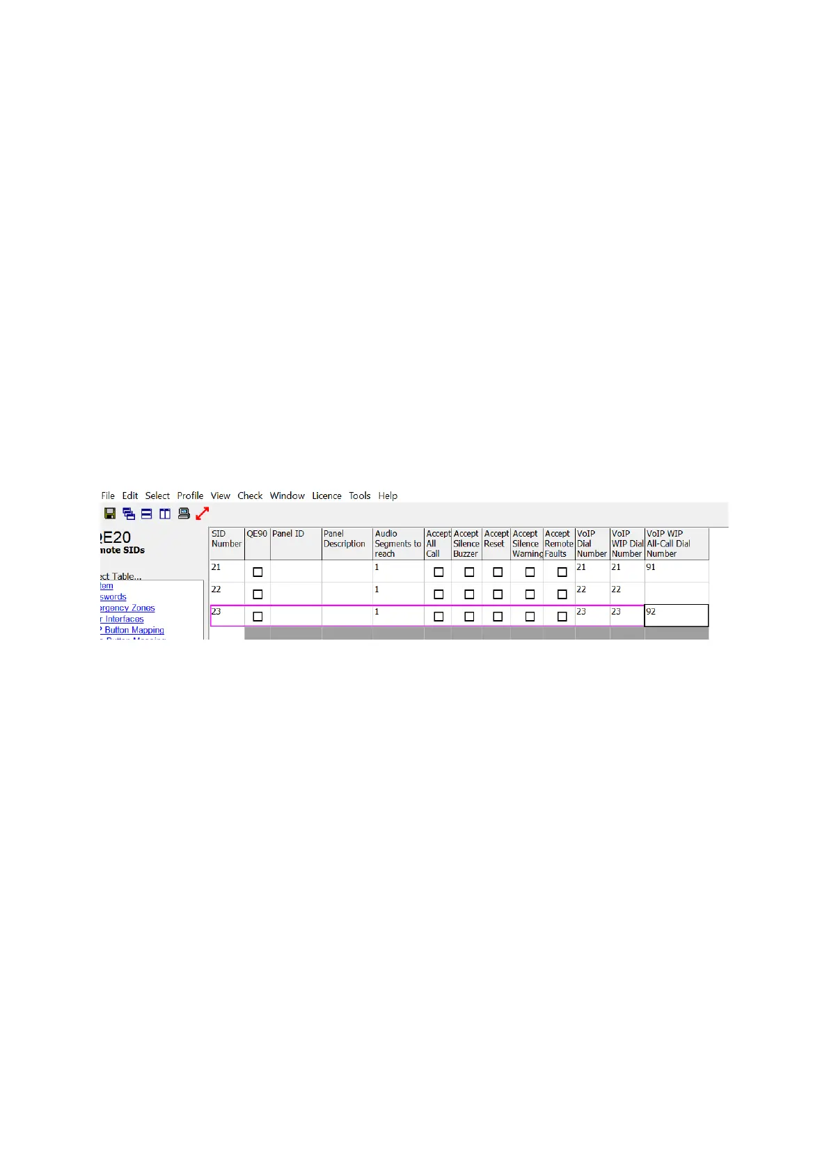
The screenshot in Figure 5 shows an example set up of “VoIP Dial Numbers”. This
QE20 needs to receive WIP All-Call from SIDs 21 and 23. Specific dial numbers (91
and 92) have been entered to reach the PIB VoIP Proxy at the remote QE20s for
this.
Refer to Section 3.5.1 for how to design the dial plan – the conversion of the dialled
number to IP address and port number.
Figure 5 – Example QE20 Remote SIDs Configuration
3.1.7 Configuration for “Idle Lines”
The “Idle Line” is the line on which the VIF listens for an incoming call when it is idle.
The VIF will always call out on Line 1 when it needs to originate a call.
In general, both the PA and WIP Idle Lines should be sent to “Line 1” in QE20Config.
3.1.8 Configuration for Paging Console Audio and Music Distribution
It is not possible to change the idle state of the 2nd lines of the VIF, as this forces the
line relay to be switched to the 2nd line. This is not a problem as systems utilising
the VoIP PIB Proxy function shouldn’t require this 2nd line. The VIF, VoIP PIB proxy,
and ATA lines can be used to distribute paging console audio and music over fibre,
in a very similar way to emergency PA and WIP audio. This is controlled by scripting
in the QE20 configuration. Refer to Section 3.6 for an example.
3.1.9 Configuration for a Fibre-Copper Bridge
In a mixed copper / Fibre network there needs to be one QE20 with both a Fibre
interface and an RS485 Copper interface for each copper segment. This QE20 is
called a Fibre-Copper Bridge and will have 2 Network Modules fitted.
• Panels on the copper segment that don’t have the fibre interface will send a
message to the Fibre-Copper Bridge QE20 when a call is required on the fibre