Chapter 5 238-2BC00 - Combination module Manual VIPA System 200V
5-22 HB97E - SM-AIO - Rev. 12/32
The digital part gets its data from the CPU in form of a 16byte data block.
The data block has the following structure:
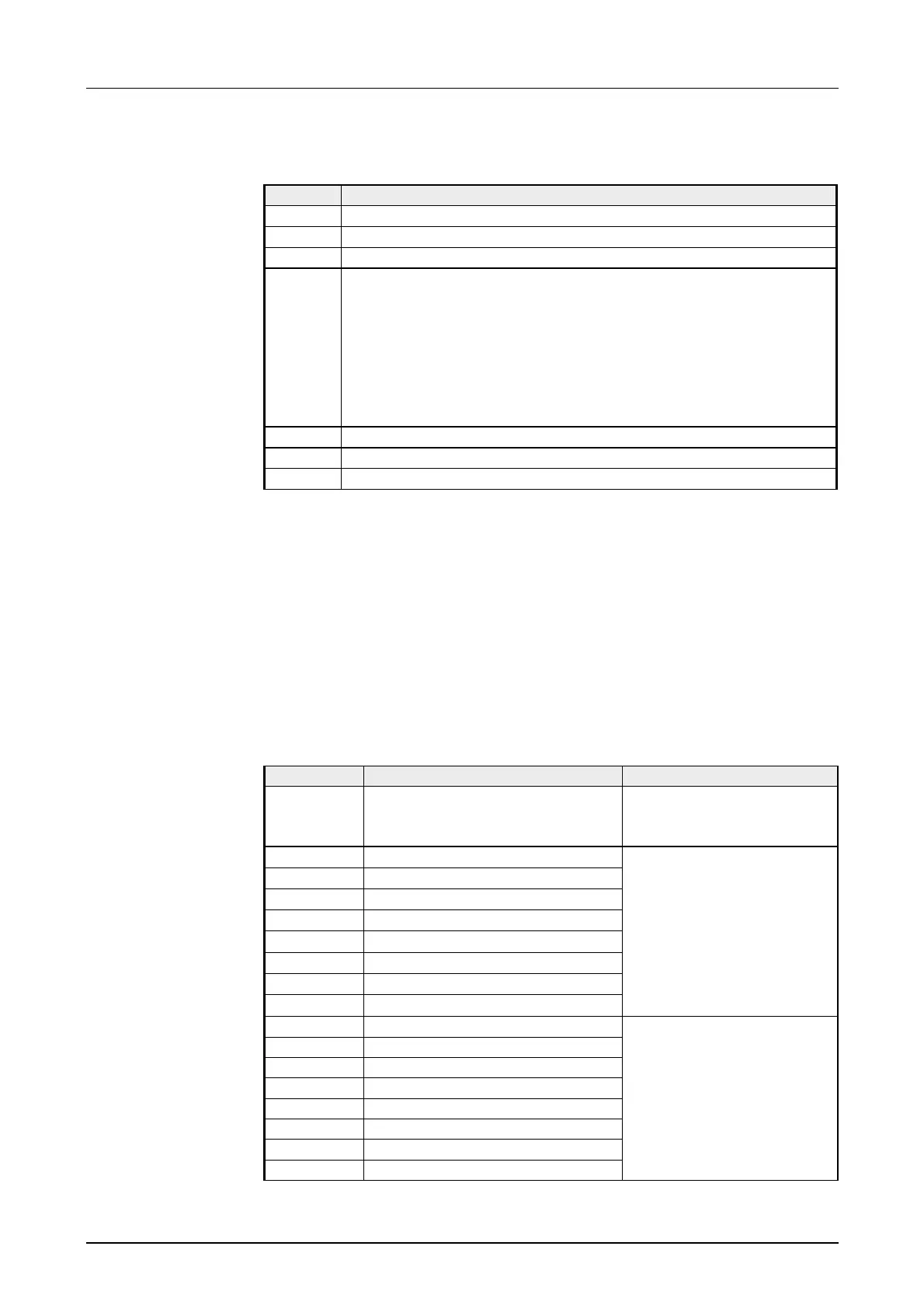
Byte Description
0 ... 3 Value counter 1
4 ... 7 Value counter 2
8 ... 11 Value counter 3
12 Bit 0: Output Bit Q.12 / Release counter output 1
1)
Bit 1: Output Bit Q.13 / Release counter output 2
Bit 2: Output Bit Q.14 / Release counter output 3
Bit 3: Output Bit Q.15
Bit 4: Software Gate counter 1
Bit 5: Software Gate counter 2
Bit 6: Software Gate counter 3
Bit 7: not evaluated
13 Command for counter 1
14 Command for counter 2
15 Command for counter 3
1)
The outputs may only be used as digital output if you parameterized them as "output" in the basic
parameterization.
After transmitting a command, the respective counter confirms the
successful processing of the command by setting the corresponding
handshake bit. To enable the respective counter to accept a new
command, you have to transmit the command 00h to the counter. After
writing the command 00h, the handshake bit assigned to this counter will
be reset. The counter is released for a new command.
The following commands are available:
Command Function Description
00h Reset command handshake
Release for a new
command (must precede
each command)
A0h Set counter value
A1h Set load value
A2h Set comparison value
A3h Set end value
A4h Set latch value
A5h Set hysteresis value
A6h Set value of pulse duration
A7h reserved
By means of these
commands, a value set
under "Value counter ..." is
transferred to the
according register of a
counter.
80h Counter value
81h Load value
82h Comparison value
83h End value
84h Latch (display latch value)
85h Hysteresis value
86h Pulse duration value
87h reserved
These commands cause
the counter to send back a
certain register value in
the input image of the
corresponding counter.
Data to digital part
(output image)
Communication via
handshake bit
Command overview