Manual VIPA System 200V Chapter 5 238-2BC00 - Combination module
HB97E - SM-AIO - Rev. 12/32 5-23
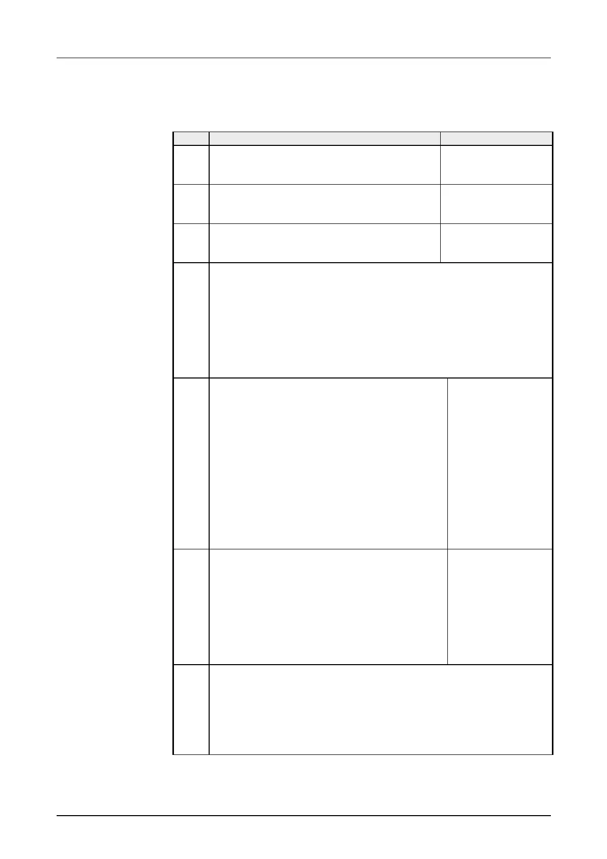
The module sends back a 16byte input image that maps into the memory
area of the CPU. The structure of input data depends on counter activation:
Byte Counter activated Counter deactivated
0 ... 3 Image counter 1 Byte 0 ... 2: 0
Byte 3: Bit 0: I.0
Bit 1: I.1
4 ... 7 Image counter 2 Byte 4 ... 6: 0
Byte 7: Bit 0: I.2
Bit 1: I.3
8 ...
11
Image counter 3 Byte 8 ... 10: 0
Byte 11: Bit 0: I.4
Bit 1: I.5
12 Gate/Latch
Bit 0: Input I.6: Status input HW gate counter 1
Bit 1: Input I.8: Status input HW gate counter 2
Bit 2: Input I.10: Status input HW gate counter 3
Bit 3: 0 (fix)
Bit 4: Input I.7: Status input Latch 1
Bit 5: Input I.9: Status input Latch 2
Bit 6: Input I.11: Status input Latch 3
Bit 7: 0 (fix)
13
Internal gate / last counter direction
If the counter operating mode is set to "off", these
Bits are "0".
Bit 0: Status internal gate 1
Bit 1: Status internal gate 2
Bit 2: Status internal gate 3
Bit 3: 0 (fix)
Bit 4: 0= counter direction counter 1 down
1= counter direction counter 1 up
Bit 5: 0= counter direction counter 2 down
1= counter direction counter 2 up
Bit 6: 0= counter direction counter 3 down
1= counter direction counter 3 up
Bit 7: 0 (fix)
0
14 Status of the counter outputs/command handshake
Bit 0: Status internal counter output counter 1
Bit 1: Status internal counter output counter 2
Bit 2: Status internal counter output counter 3
Bit 3: 0 (fix)
Bit 4: Status command handshake counter 1
Bit 5: Status command handshake counter 2
Bit 6: Status command handshake counter 3
Bit 7: 0 (fix)
0
15 Status inputs
If the channel is set as output, the according Bit is "0"
Bit 0: Status input I.12
Bit 1: Status input I.13
Bit 2: Status input I.14
Bit 3: Status input I.15
Bit 7 ... 4: 0 (fix)
Data from digital
part (input image)