Chapter 2 Analog input modules Manual VIPA System 200V
2-6 HB97E - SM-AIO - Rev. 12/32
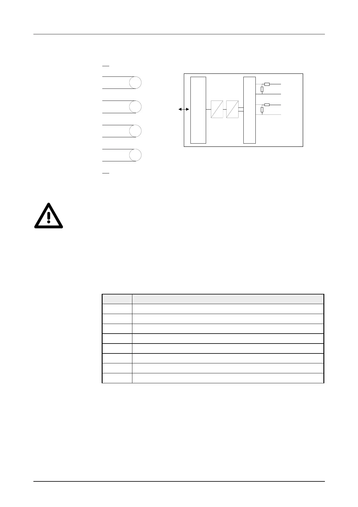
Wiring diagram Schematic diagram
1
2
3
4
5
6
7
8
9
10
V
V
V
V
V-Bus
Input
µP
Channel 0
2
3
Mux
Channel 1
4
5
.
.
.
D
A
Attention!
Temporarily not used inputs have to be connected with the concerning
ground at activated channel. When deactivating unused channels by
means of FFh, this is not required.
During a measurement the data is stored in the data input area.
The following figure shows the structure of the data input area:
Data input area:
Byte Bit 7 ... Bit 0
0 High-Byte channel 0
1 Low-Byte channel 0
2 High-Byte channel 1
3 Low-Byte channel 1
4 High-Byte channel 2
5 Low-Byte channel 2
6 High-Byte channel 3
7 Low-Byte channel 3
Wiring and
schematic
diagram
Measurement data
acquisition