n For every channel the measuring data are stored as word in the
data input range.
n For the output you have to enter a value as word into the data
output range.
Used area
Ä
‘Input area’ on page 132
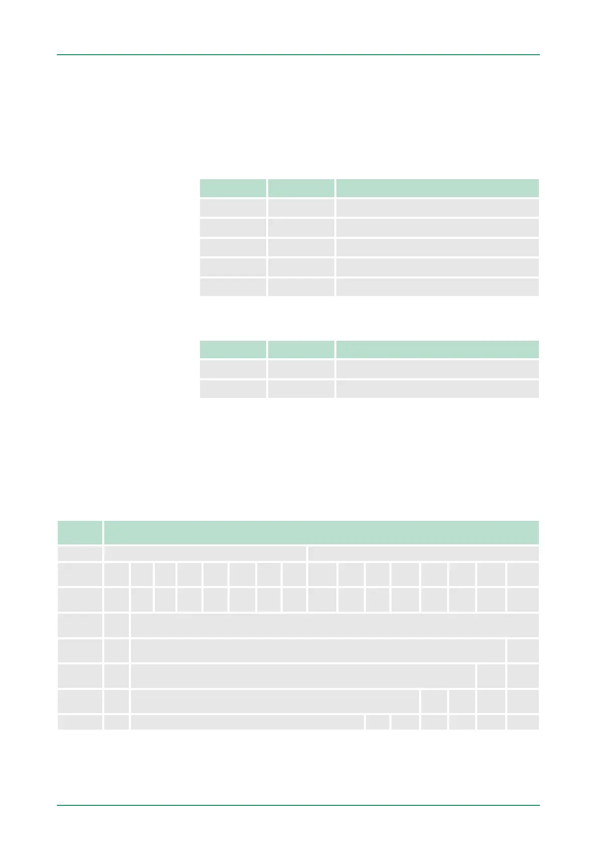
Address Access Assignment
+4 Word Analog input CH0
+6 Word Analog input CH1
+8 Word Analog input CH2
+10 Word Analog input CH3
+12 Word Analog input CH4
Used area
Ä
‘Output area’ on page 133
Address Access Assignment
+4 Word Analog output CH0
+6 Word Analog output CH1
The analog values are represented in two’s complement format.
Depending on the parametrized transformation speed the lowest
value bits of the measuring value are irrelevant. With increasing sam-
pling rate, the resolution decreases. The following table lists the reso-
lution in dependence of the sampling rate. The lowest value irrelevant
bits of the output value are marked with "X".
Resolu-
tion
Analog value
High byte (byte 0) Low byte (byte 1)
Bit
number
15 14 13 12 11 10 9 8 7 6 5 4 3 2 1 0
Signifi-
cance
sign
2
14
2
13
2
12
2
1
1
2
10
2
9
2
8
2
7
2
6
2
5
2
4
2
3
2
2
2
1
2
0
15bit +
sign
sign Relevant output value (at 3.7 ... 30Hz)
14bit +
sign
sign Relevant output value (at 60Hz) X
13bit +
sign
sign Relevant output value (at 120Hz) X X
11bit +
sign
sign Relevant output value (at 170Hz) X X X X
9bit + sign sign Relevant output value (at 200Hz) X X X X X X
For the sign bit is valid:
Numeric notation in Sie-
mens S7 format
Algebraic sign bit (sign)
VIPA System 300S Deployment I/O periphery
Analog part
HB140 | CPU | 314-6CF03 | GB | 16-43 135