6.4 Analog part
The analog part consists of 4 input, 1 Pt100 and 2 output channels.
10byte input and 4byte output data of the process image are used by
the analog part. The channels of the module are galvanically sepa-
rated from the SPEEDBus via DC/DC transducer and opto couplers.
CAUTION!
T
emporarily not used analog inputs with activated
channel must be connected to the concerning ground.
To avoid measuring errors, you should connect only
one measuring type per channel.
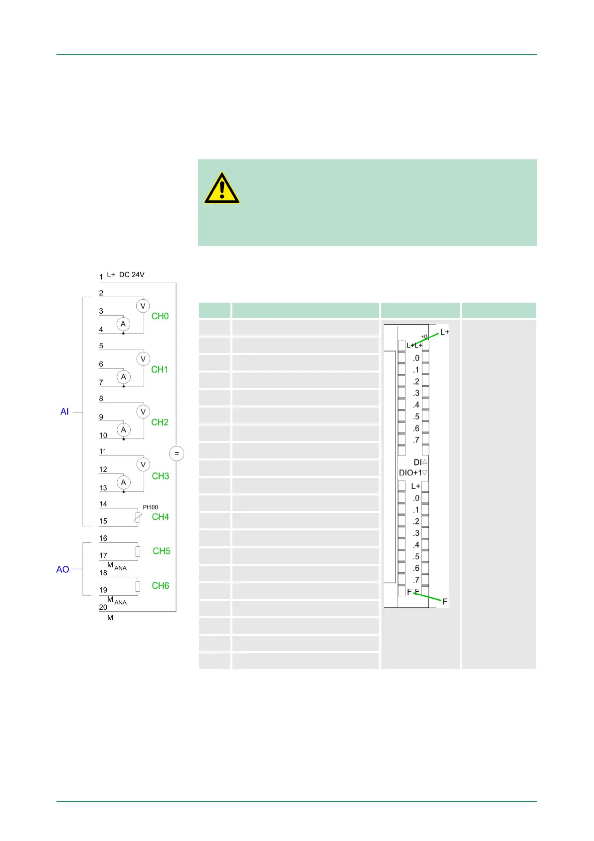
CPU 314-6CF03: Analog part pin assignment and status indi-
cator
Pin Assignment LEDs Description
1 Power supply DC 24V AIO
1L+
LED (green)
Supply voltage
available
F
LED (red)
Sum error
2 Voltage measurement channel 0
3 Current measurement channel 0
4 Ground channel 0
5 Voltage measurement channel 1
6 Current measurement channel 1
7 Ground channel 1
8 Voltage measurement channel 2
9 Current measurement channel 2
10 Ground channel 2
11 Voltage measurement channel 3
12 Current measurement channel 3
13 Ground channel 3
14 Pt 100 channel 4
15 Pt 100 channel 4
16 Output + channel 5
17 Ground output channel 5
18 Output + channel 6
19 Ground output channel 6
20 Ground power supply AIO
n By including the SPEEDBUS.GSD in your hardware configurator
,
the module is at your disposal in the hardware catalog. After the
installation of the GSD you will find the CPU 314-6CF03 at
‘Additional field devices è I/O è VIPA_SpeedBus’.
n If there is no hardware configuration available, the in- and output
areas starting with address 1024 are mapped to the address
range of the CPU.
Overview
Access to the analog
part
VIPA System 300SDeployment I/O periphery
Analog part
HB140 | CPU | 314-6CF03 | GB | 16-43 134