5.3.3 Address assignment I/O part
n By including the SPEEDBUS.GSD in your hardware configurator
,
the module is at your disposal in the hardware catalog. After the
installation of the GSD you will find the CPU 314-6CF03 at
‘Additional field devices è I/O è VIPA_SpeedBus’.
n In case there is no hardware configuration available, the in- and
output areas starting at address 1024 are shown in the address
range of the CPU.
n For the data input a range of 48byte and for the data output a
range of 24byte is available
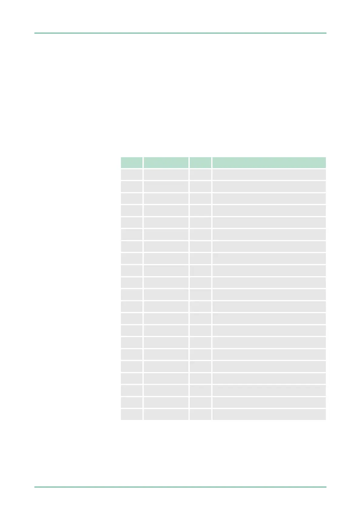
Input area
Addr. Name Byte Function
+0 DI_0 1 Digital input I+0.0 ... I+0.7
+1 DI_1 1 Digital input I+1.0 ... I+1.7
+2 - 2 reserved
+4 AI_CH0 2 Analog input CH0
+6 AI_CH1 2 Analog input CH1
+8 AI_CH2 2 Analog input CH2
+10 AI_CH3 2 Analog input CH3
+12 AI_CH4 2 Analog input CH4
+14 - 2 reserved
+16 CVCL_0 4 Counter/Latch value 0
+20 - 2 reserved
+22 ISTS_0 2 Input status counter 0
+24 CVCL_1 4 Counter/Latch value 1
+28 - 2 reserved
+30 ISTS_1 2 Input status counter 1
+32 CVCL_2 4 Counter/Latch value 2
+36 - 2 reserved
+38 ISTS_2 2 Input status counter 2
+40 CVCL_3 4 Counter/Latch value 3
+44 - 2 reserved
+46 ISTS_3 2 Input status counter 3
Overview
VIPA System 300SDeployment CPU 314-6CF03
Addressing > Address assignment I/O part
HB140 | CPU | 314-6CF03 | GB | 16-43 58