5.3 Addressing
5.3.1
Overview
To provide specific addressing of the installed peripheral modules,
certain addresses must be allocated in the CPU. At the start-up of the
CPU, this assigns automatically peripheral addresses for digital in-/
output modules starting with 0 and ascending depending on the slot
location. If no hardware project engineering is available, the CPU
stores at the addressing analog modules to even addresses starting
with 256. Modules at the SPEED-Bus are also taken into account at
the automatic address allocation. Here the digital I/Os are stored
beginning with address 128 and analog I/Os, FMs and CPs beginning
with address 2048.
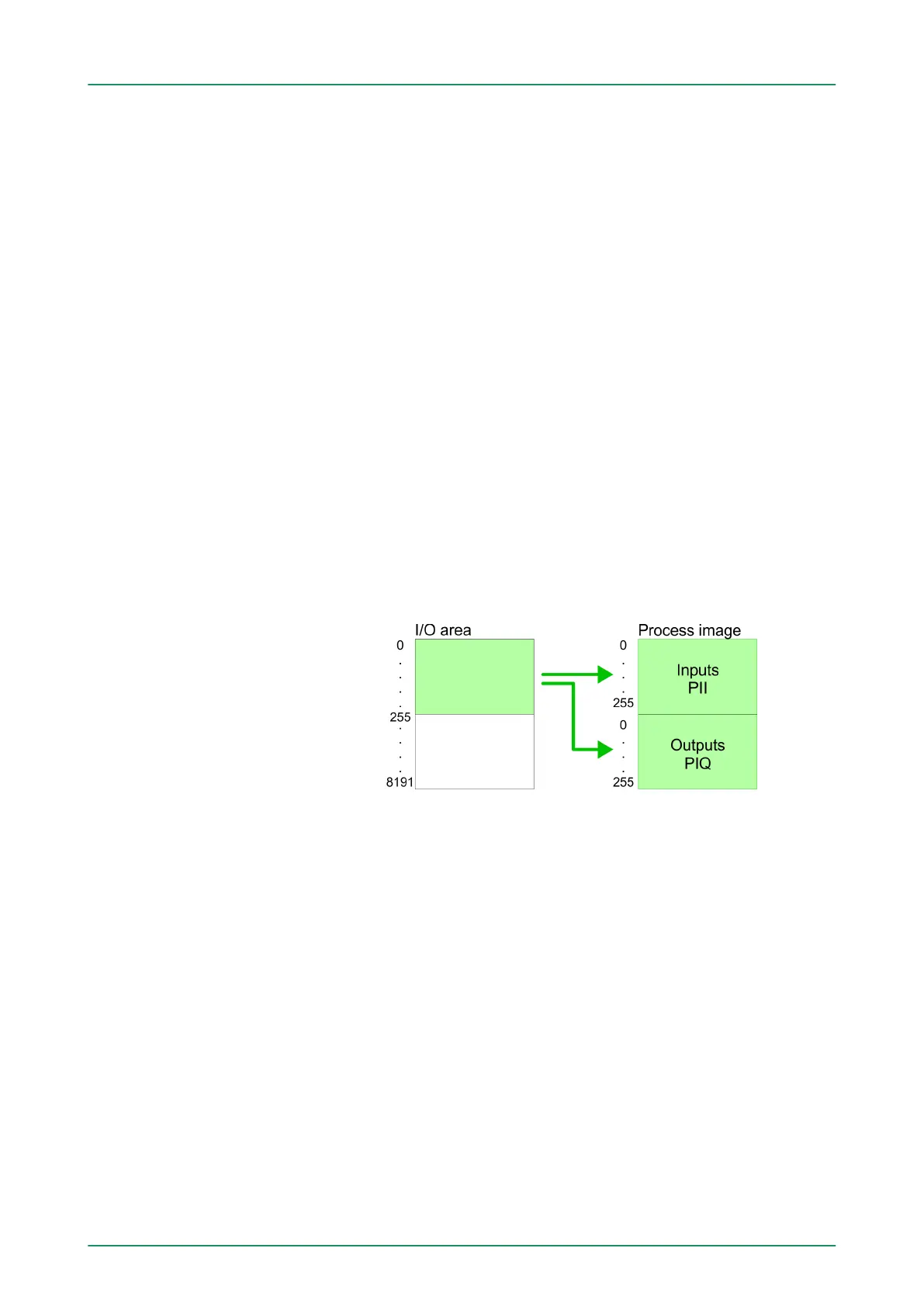
5.3.2 Addressing
The CPU 314-6CF03 provides an I/O area (address 0 ... 8191) and a
process image of the in- and outputs (each address 0 ... 255). The
process image stores the signal states of the lower address (0 ... 255)
additionally in a separate memory area.
The process image this divided into two parts:
n process image to the inputs (PII)
n process image to the outputs (PIQ)
The process image is updated automatically when a cycle has been
completed.
Maximally 8 modules per row may be configured by the CPU
314-6CF03.
For the project engineering of more than 8 modules you may use line
interface connections. For this you set in the hardware configurator
the module IM 360 from the hardware catalog to slot 3 of your 1. pro-
file rail. Now you may extend your system with up to 3 profile rails by
starting each with an IM 361 from Siemens at slot 3. Considering the
max total current with the CPU 314-6CF03 from VIP
A up to 32
modules may be arranged in a row. Here the installation of the line
connections IM 360/361 from Siemens is not required.
Further 10 modules at the SPEED-Bus may be connected. CPs and
DP masters that are additionally virtual configured at the standard bus
are taken into the count of 32 modules at the standard bus.
Backplane bus
periphery
Max. number of plug-
gable modules
VIPA System 300S Deployment CPU 314-6CF03
Addressing > Addressing
HB140 | CPU | 314-6CF03 | GB | 16-43 55