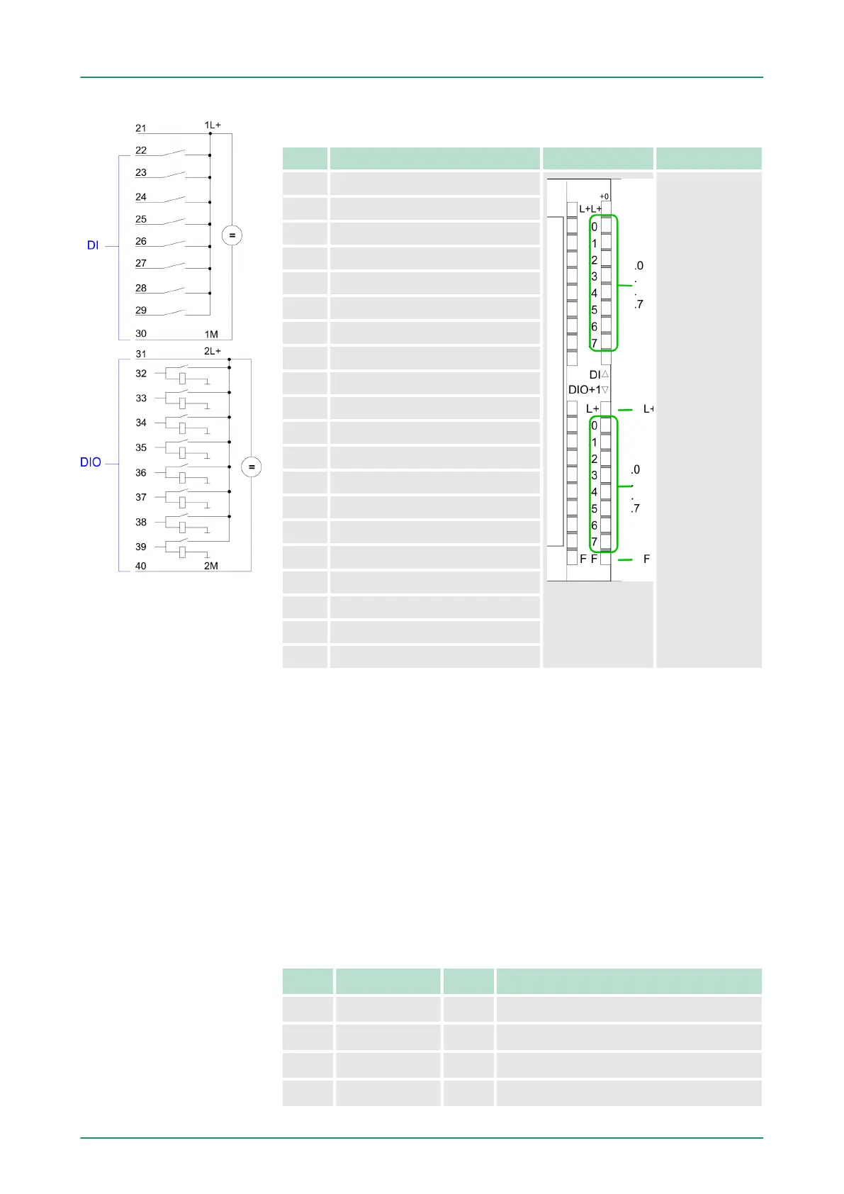
CPU 314-6CF03: Digital part pin assignment and status indicator
Pin Assignment LEDs Description
21 Power supply +DC 24 V DI DI:
.0 ... .7
LED (green)
I+0.0 ... I+0.7
starting with ca.
15V the signal
"1" at the input is
recognized and
the according
LED is activated
DIO:
2L+
LED (green)
Supply voltage
available for DIO
.0 ... .7
LED (green)
I/Q+1.0 ... I/Q
+1.7
on at active
output/input
F
LED (red)
Overload or
short circuit error
22 I+0.0 / Counter 0(A)
23 I+0.1 / Counter 0(B)
24 I+0.2 / Gate0/Latch0/Reset0
25 I+0.3 / Counter 1(A)
26 I+0.4 / Counter 1(B)
27 I+0.5 / Gate1/Latch1/Reset1
28 I+0.6 / Counter 2(A)
29 I+0.7 / Counter 2(B)
30 Ground DI
31 Power supply +DC 24 V DIO
32 I/Q+1.0 / Gate2/Latch2/Reset2
33 I/Q+1.1 / Counter 3(A)
34 I/Q+1.2 / Counter 3(B)
35 I/Q+1.3 / Gate3/Latch3/Reset3
36 I/Q+1.4 / OUT0/Latch0/Reset0
37 I/Q+1.5 / OUT1/Latch1/Reset1
38 I/Q+1.6 / OUT2/Latch2/Reset2
39 I/Q+1.7 / OUT3/Latch3/Reset3
40 Ground DIO
6.3 Address assignment I/O part
n By including the SPEEDBUS.GSD in your hardware configurator
,
the module is at your disposal in the hardware catalog. After the
installation of the GSD you will find the CPU 314-6CF03 at
‘Additional field devices è I/O è VIPA_SpeedBus’.
n In case there is no hardware configuration available, the in- and
output areas starting at address 1024 are shown in the address
range of the CPU.
n For the data input a range of 48byte and for the data output a
range of 24byte is available
Input area
Addr. Name Byte Function
+0 DI_0 1 Digital input I+0.0 ... I+0.7
+1 DI_1 1 Digital input I+1.0 ... I+1.7
+2 - 2 reserved
+4 AI_CH0 2 Analog input CH0
Overview
VIPA System 300SDeployment I/O periphery
Address assignment I/O part
HB140 | CPU | 314-6CF03 | GB | 16-43 132