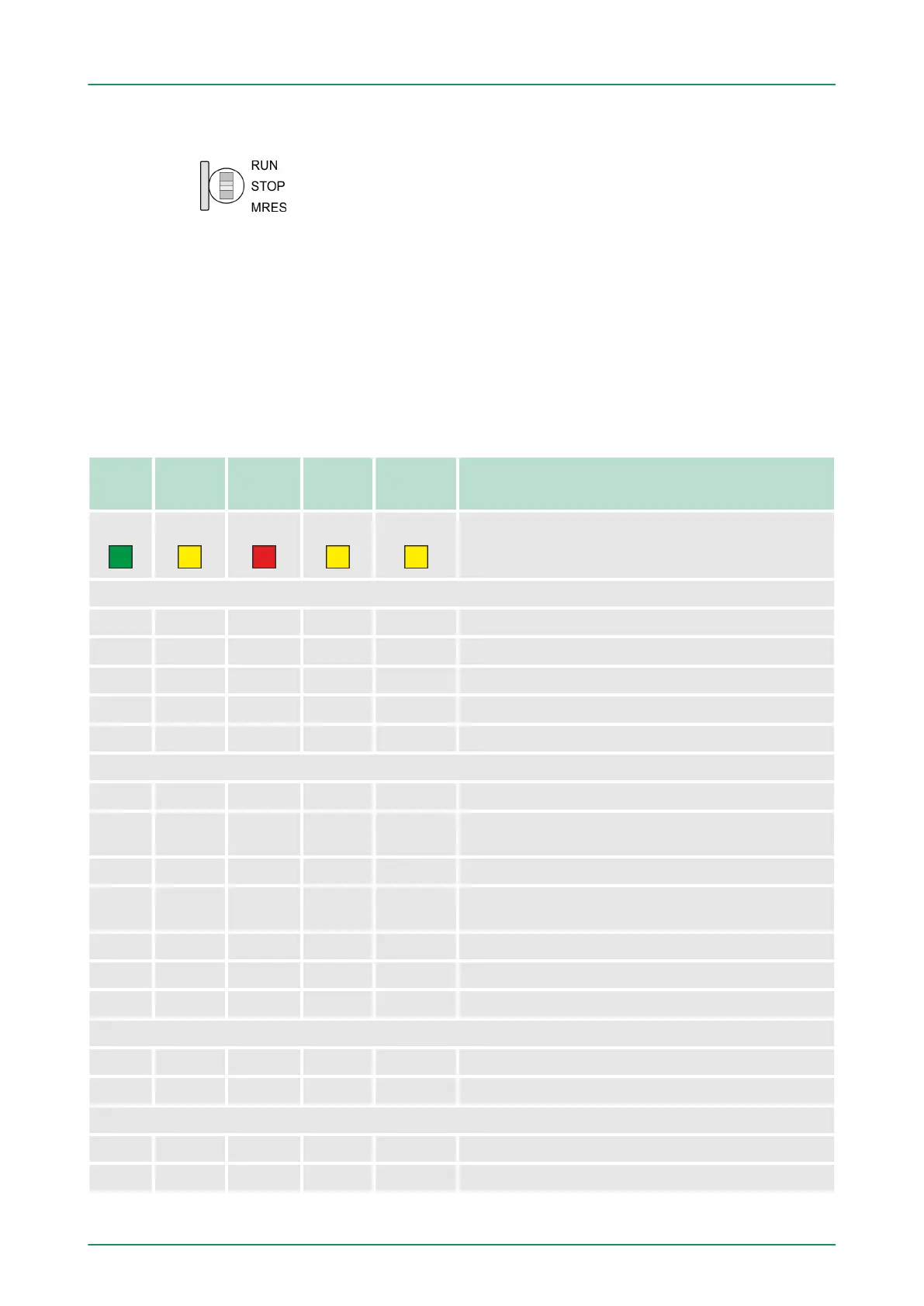
4.2.6 Operating mode switch
n With the operating mode switch you may switch the CPU between
ST
OP and RUN.
n During the transition from STOP to RUN the operating mode
START-UP is driven by the CPU.
n Placing the switch to MRES (Memory Reset), you request an
overall reset with following load from MMC, if a project there
exists.
4.2.7 LEDs
As soon as the CPU is supplied with 5V
, the green PW-LED (Power)
is on.
RN
(RUN)
ST
(ST
OP)
SF
(SFAIL)
FC
(FRCE)
MC
(MMC)
Meaning
green
yellow red yellow yellow
Boot-up after PowerON
● BB* ● ● ● * Blinking with 10Hz: Firmware is loaded.
● ● ● ● ● Initialization: Phase 1
● ● ● ● ○ Initialization: Phase 2
● ● ● ○ ○ Initialization: Phase 3
○ ● ● ○ ○ Initialization: Phase 4
Operation
○ ● X X X CPU is in STOP state.
BB ● X X X CPU is in start-up state, the RUN LED blinks during
operating OB100 at least for 3s.
● ○ ○ X X CPU is in state RUN without error.
X X ● X X There is a system fault. More information may be
found in the diagnostics buf
fer of the CPU.
X X X ● X Variables are forced.
X X X X ● Access to the memory card.
X BB* ○ ○ ○ * Blinking with 10Hz: Configuration is loaded.
Overall reset
○ BB X X X Overall reset is requested.
○ BB* X X X * Blinking with 10Hz: Overall reset is executed.
Factory reset
● ● ○ ○ ○ Factory reset is executed.
○ ● ● ● ● Factory reset finished without error.
LEDs CPU
VIPA System 300SHardware description
Structure > LEDs
HB140 | CPU | 314-6CF03 | GB | 16-43 36