CAUTION!
Please regard that the voltage at an output channel is
always £ the supply voltage connected to L+. Please
regard also that due to the parallel connection of in-
and output channel for each group one set output can
be supplied via a connected input signal. A thus con-
nected output remains active even with shut down
supply voltage. Non-observance may cause damages
of the module.
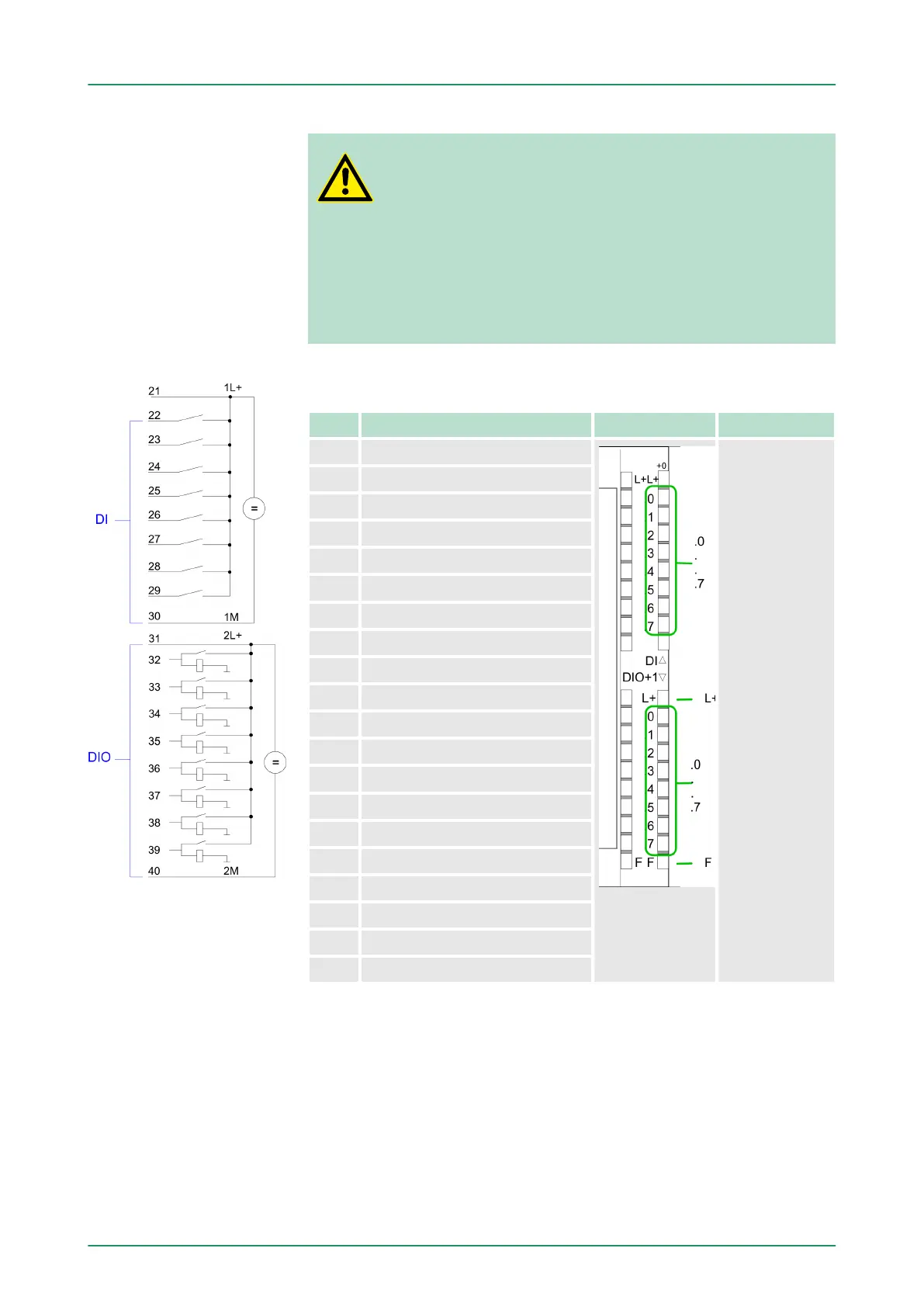
CPU 314-6CF03: Digital part pin assignment and status indicator
Pin Assignment LEDs Description
21 Power supply +DC 24 V DI
DI:
.0 ... .7
LED (green)
I+0.0 ... I+0.7
starting with ca.
15V the signal
"1" at the input is
recognized and
the according
LED is activated
DIO:
2L+
LED (green)
Supply voltage
available for DIO
.0 ... .7
LED (green)
I/Q+1.0 ... I/Q
+1.7
on at active
output/input
F
LED (red)
Overload or
short circuit error
22 I+0.0 / Counter 0(A)
23 I+0.1 / Counter 0(B)
24 I+0.2 / Gate0/Latch0/Reset0
25 I+0.3 / Counter 1(A)
26 I+0.4 / Counter 1(B)
27 I+0.5 / Gate1/Latch1/Reset1
28 I+0.6 / Counter 2(A)
29 I+0.7 / Counter 2(B)
30 Ground DI
31 Power supply +DC 24 V DIO
32 I/Q+1.0 / Gate2/Latch2/Reset2
33 I/Q+1.1 / Counter 3(A)
34 I/Q+1.2 / Counter 3(B)
35 I/Q+1.3 / Gate3/Latch3/Reset3
36 I/Q+1.4 / OUT0/Latch0/Reset0
37 I/Q+1.5 / OUT1/Latch1/Reset1
38 I/Q+1.6 / OUT2/Latch2/Reset2
39 I/Q+1.7 / OUT3/Latch3/Reset3
40 Ground DIO
n By including the SPEEDBUS.GSD in your hardware configurator
,
the module is at your disposal in the hardware catalog. After the
installation of the GSD you will find the CPU at
‘Additional field devices è I/O è VIPA_SpeedBus’. 314-6CF03.
n If there is no hardware configuration available, the in- and output
areas starting with address 1024 are mapped to the address
range of the CPU.
n For each input bit the status is stored in the data input area.
n For the output you have to enter a value into the data output are.
Access to the digital
part
VIPA System 300SDeployment I/O periphery
Digital part
HB140 | CPU | 314-6CF03 | GB | 16-43 146