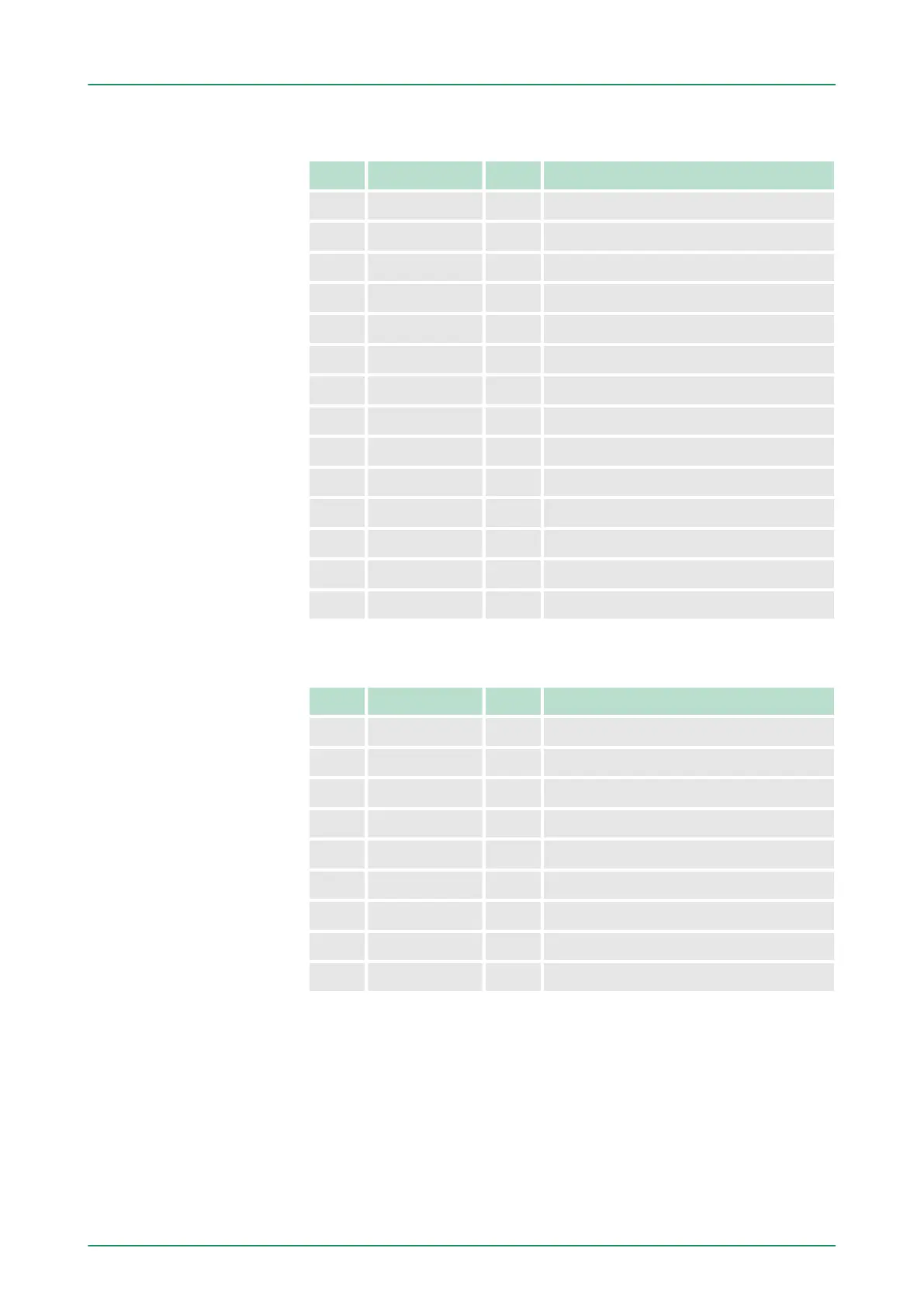
Used area
Ä
‘Input area’ on page 132
Addr. Name Byte Function
+0 DI_0 1 Digital input I+0.0 ... I+0.7
+1 DI_1 1 Digital input I+1.0 ... I+1.7
+16 CVCL_0 4 Counter value / latch value counter 0
+20 - 2 reserved
+22 ISTS_0 2 Input status counter 0
+24 CVCL_1 4 Counter value / latch value counter 1
+28 - 2 reserved
+30 ISTS_1 2 Input status counter 1
+32 CVCL_2 4 Counter value / latch value counter 2
+36 - 2 reserved
+38 ISTS_2 2 Input status counter 2
+40 CVCL_3 4 Counter value / latch value counter 3
+44 - 2 reserved
+46 ISTS_3 2 Input status counter 3
Used area
Ä
‘Output area’ on page 133
Addr. Name Byte Function
+0 - 1 reserved
+1 DO_1 1 Digital output Q+1.0 ... Q+1.7
+10 OSTS_0 2 Output status counter 0
+12 - 2 reserved
+14 OSTS_1 2 Output status counter 1
+16 - 2 reserved
+18 OSTS_2 2 Output status counter 2
+20 - 2 reserved
+22 OSTS_3 2 Output status counter 3
The counter value always contains the current value of the counter
.
An edge 0-1 at the digital Latch input stores the current counter value
in as latch value.
Counter value counter
X
Latch value counter
X
VIPA System 300SDeployment I/O periphery
Counter - In-/output area
HB140 | CPU | 314-6CF03 | GB | 16-43 150