4. T
o connect the SPEED-Bus modules, plug it between the trian-
gular positioning helps to a slot marked with "SLOT ..." and pull
it down.
5. Fix the CPU by screwing.
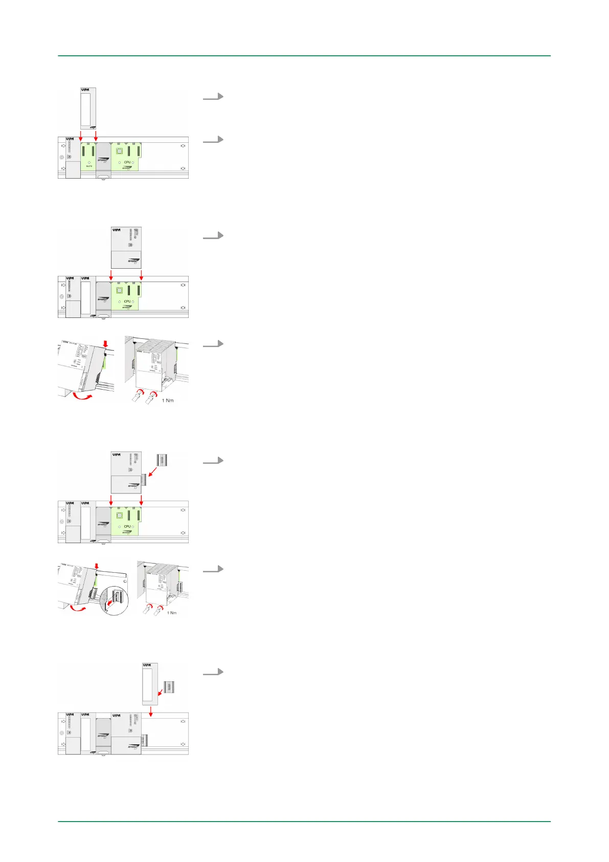
1. T
o deploy the SPEED7-CPU exclusively at the SPEED-Bus,
plug it between the triangular positioning helps to the slot
marked with "CPU SPEED7" and pull it down.
2. Fix the CPU by screwing.
1. If also standard modules shall be plugged, take a bus coupler
and click it at the CPU from behind like shown in the picture.
Plug the CPU between the triangular positioning helps to the slot
marked with "CPU SPEED7" and pull it down.
2. Fix the CPU by screwing.
Repeat this procedure with the peripheral modules, by clicking a
backplane bus coupler
, stick the module right from the modules
you've already fixed, click it downwards and connect it with the
backplane bus coupler of the last module and bolt it.
Installation CPU without
Standard-Bus-Modules
Installation CPU with
Standard-Bus-Modules
Installation Standard-
Bus-Modules
VIPA System 300SAssembly and installation guidelines
Assembly SPEED-Bus
HB140 | CPU | 314-6CF03 | GB | 16-43 22