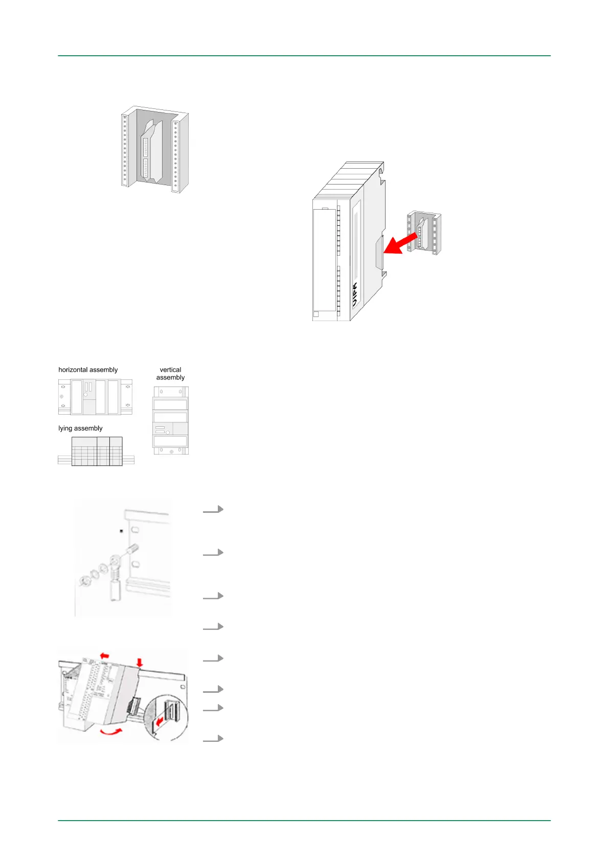
For the communication between the modules the System 300S uses
a backplane bus connector
. Backplane bus connectors are included
in the delivering of the peripheral modules and are clipped at the
module from the backside before installing it to the profile rail.
Please regard the allowed environment temperatures:
n horizontal assembly: from 0 to 60°C
n vertical assembly: from 0 to 40°C
n lying assembly: from 0 to 40°C
1. Bolt the profile rail with the background (screw size: M6), so that
you still have minimum 65mm space above and 40mm below
the profile rail.
2. If the background is a grounded metal or device plate, please
look for a low-impedance connection between profile rail and
background.
3. Connect the profile rail with the protected earth conductor
. For
this purpose there is a bolt with M6-thread.
4. The minimum cross-section of the cable to the protected earth
conductor has to be 10mm
2
.
5. Stick the power supply to the profile rail and pull it to the left side
to the grounding bolt of the profile rail.
6. Fix the power supply by screwing.
7. T
ake a backplane bus connector and click it at the CPU from the
backside like shown in the picture.
8. Stick the CPU to the profile rail right from the power supply and
pull it to the power supply
.
Bus connector
Assembly possibilities
Approach
VIPA System 300SAssembly and installation guidelines
Assembly standard bus
HB140 | CPU | 314-6CF03 | GB | 16-43 24