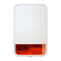
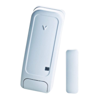
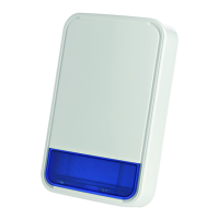
SMD-426, SMD-427
D-302758 25
Battery cover
Open battery cover and
connect the battery to its
terminals (without
insulator). Verify proper
polarity.
3 volts CR123A
Tamper
switch
Enroll
button
Figure 9a. Battery Connection for CR123A
Battery cover
Open battery cover and connect the battery to its terminals.
3 volts CR17450
Tamper
switch
Enroll
button
Figure 9b. Battery Connection for CR17450
Note: When the battery first makes contact, the alarm horn may sound for one second. This indicates that the
battery is connected properly.
Close the cover, then press the test button (see fig. 1) for about 2 seconds, (for further details see par. 3.6).
3.6 Resetting the Transceiver Module
The detector has a wall / rear tamper switch to alert removal of detector. The tamper switch actuator, extending
through a hole in the base (see Figures 9a and 9b), is pressed against the bracket when the unit is attached to the
bracket.
Removal of the unit from the bracket will cause the switch contacts to open, creating a tamper event, which will
be reported by the transceiver to the control panel.
4. ENROLLMENT
Refer to the PowerMaster-10 Installer Guide for the device enrollment procedure.

 Loading...
