52
Installation
Installation
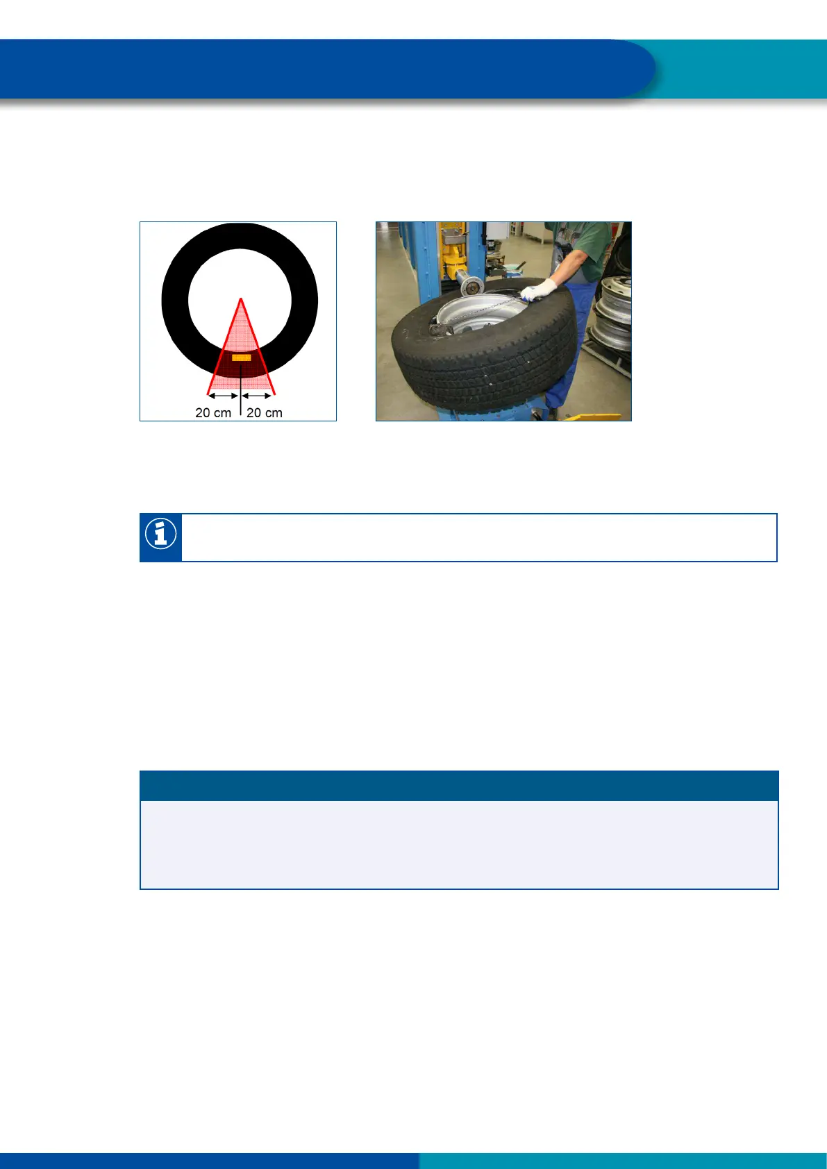
During assembly the assembly head must have a minimum distance of 20 cm to the internal sensor
(Figure 10). The remaining part of the bead can be pressed over the rim ange in the normal way
(Figure 11).
Figure 10
Figure 11
5. Then remove the complete wheel from the assembly machine.
6. Inate the tire as usual.
If a lling bell is used, the tire must not exert any pressure on the internal sensor housing or
get stuck on the housing.
Assembly of the wheel
– Fit the complete wheel to the vehicle. When doing this, apply the tightening torques specied by
the vehicle manufacturer.
7.6 Mounting the ECU in bus / towing vehicle
ECU position on vehicle
NOTICE
Damage to the vehicle frame due to welding
Welding work for mounting the bracket (WABCO part number 446 220 000 4) may affect the strength
of the vehicle frame.
– Screw the bracket to the vehicle.
Towing vehicle
The ECU connector must point to right or left only and not up, to the rear or down. The maximum
distance to a wheel for an internal sensor (WIS) must not be more than
3 m, with an internal sensor (SMS) not more than 2.25 m. For external sensors (WM2) it is
recommended to mount the ECU in front of the rst axle with twin tyres or SuperSingle tires.
– Choose the tting position in accordance with the gure "Assembly on the longitudinal beam".
– If the vehicle is equipped with a low lying coupling for central axle trailer, install the ECU on the
right side of the vehicle, so that the wireless connection to the trailer is not shielded of by the
coupling.