24
VERSION 01/2018
ORDER NUMBER DOC 2340851
Cobra 40-10 / 40-25
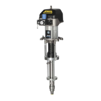
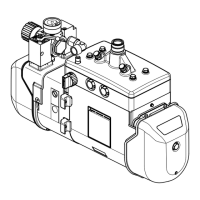
5.6 COBRA PRESSURE REGULATOR UNIT
Designation
B_04300
2
3
1
4
5
1 Pressure regulator
2 Ball valve
3 Pressure gauge
4 Compressed air Inlet
5 AirCoat lter regulator Cobra
(accessories)
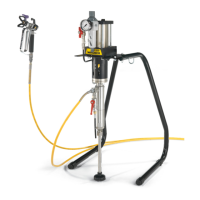
The AirCoat lter regulator must be mounted
vertically in all installation positions for the
diaphragm pump (see assembly manual for
Filter Regulator, order number2328614).
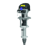
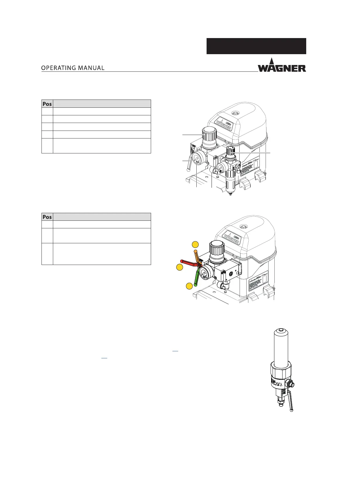
Positions of the ball valve
B_04301
2
3
1
1 Open: working position
2 Closed: the air motor can still be
under pressure.
3 Vent: Operating pressure in the air
motor is vented (control pressure is
still present).
5.6.1 HIGHPRESSURE FILTER OPTION
To ensure problem-free operation it is recommended that a WAGNER high-pressure lter
be used. These have been developed especially for WAGNER pneumatic pumps. The lter
inserts can be exchanged depending on the product to be used. The high-pressure lter
corresponding to the device can be found in Chapter; 13 and the compatible lter inserts
can be found in Chapter 14
B_06835
 Loading...