39
VERSION 01/2018
ORDER NUMBER DOC 2340851
Cobra 40-10 / 40-25
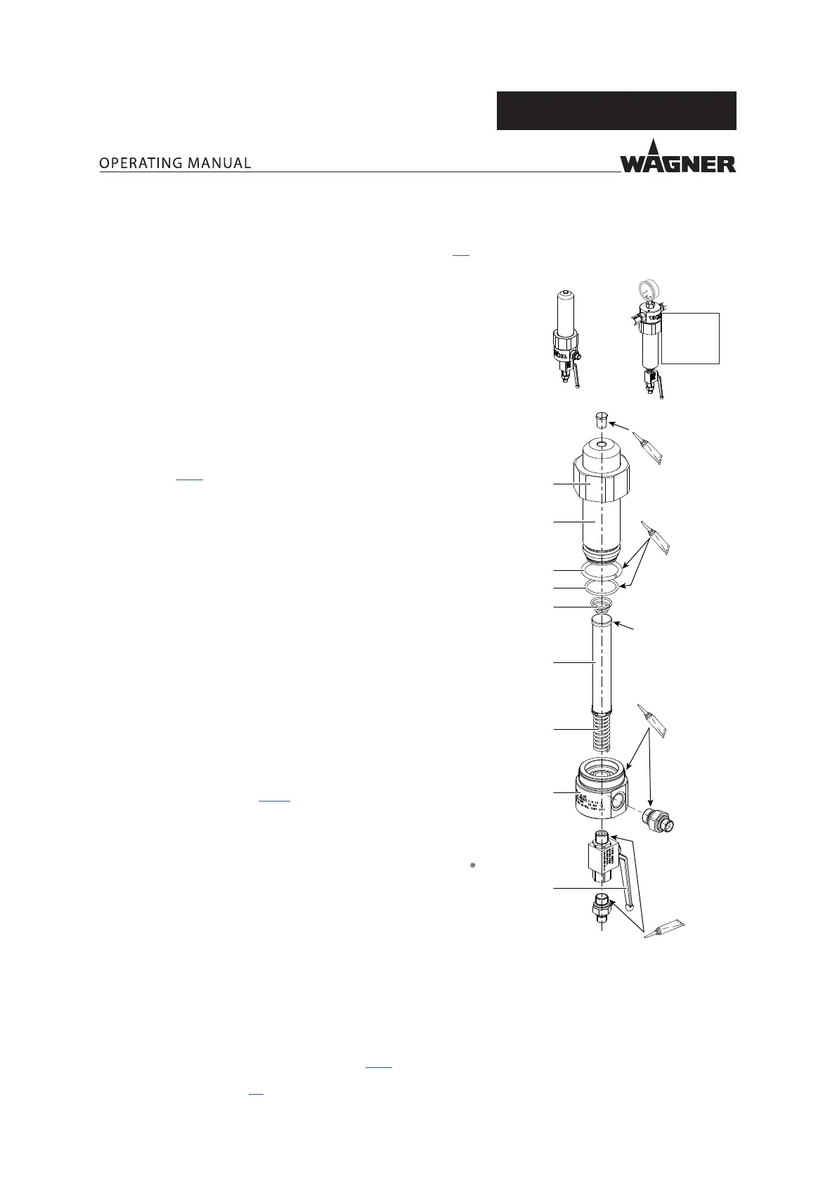
8.2.6.3 HIGHPRESSURE FILTER 530 BAR
1. Flush the pump and HP lter in accordance with Chapter 7.5, and
while doing so:
12
11
10
7
3
5
B_06836
1
21
2
Filter
identication
Mobilux EP2**
Anti-seize paste**
53MPa
530bar
7687psi
Filter installation position
Preferred Turned over
Loctite 542
Loctite 542
– At the preferred lter installation position: Flush via the
return ow valve (1). This produces a large ow. As a result,
the ushing agent also ows through the upper part of the
lter cartridge (11). Pressure regulator approx. 0.15MPa;
1.5bar; 22psi.
– At the reversed lter installation position: Flush using the
gun. This is required in the case of a reversed installation
position so that the ushing agent ows through the lter
cartridge (11). Maximize the ow (remove the nozzle, open
the dosing valve if necessary).
2. Empty the pump in a controlled manner in accordance with
Chapter 8.2.4.
3. Place the grounded collection tank under the High-pressure lter.
4. Open ball valve (1).
5. Loosen union nut (3) with a size 70 wrench.
6. Unscrew the union nut (3) and lift slightly so that it does not get
dirty in the next step.
7. Remove the lter housing (2) with the union nut (3). The cone
spring (12) remains in the lter housing (2). If the O-ring (5) is not
damaged, it remains on the lter housing (2).
8. Remove the lter cartridge (11) and lter support (10) from the
lter housing (2).
9. Clean all parts:
– Place the lter cartridge (11) and lter support (10) in solvent.
Clean using brush.
– Fill the lter housing (2) approx. 1/3 full with solvent, secure
wearing a glove and shake well.
– Clean the distribution housing (7) using a brush.
10. If necessary, replace the O-ring (5) and/or lter cartridge (11).
Order No., see Chapter 14.12.
11. Assemble all parts in reverse order. While doing so:
– Coat the thread of the distribution housing (7) with anti-seize
paste**.
– Coat the O-ring (5) and pressure ring (21) with Mobilux
EP2**.
– Observe the installation position of the lter cartridge (11):
Push the closed end with the lter identication ahead into
the lter housing (2).
– Make sure that the cone spring (12) is in the lter housing
(note the installation position). Press on the cone spring after
inserting the lter cartridge (11) and lter support (10); the
spring action must be noticeable.
– Tighten the union nut (3) by hand.
12. Close ball valve (1).
13. Fill the pump in accordance with Chapter 8.2.5.
** Order No., see Chapter 13.
 Loading...