B-6 Specifications
Auxiliary input 2 TTL signal or contact closure.
Input voltage range: ±30 Vdc.
Logic high = >3.0 Vdc ±10%.
Logic low = <1.9 Vdc ±10%.
Minimum pulse width = 100 msec.
Screw terminal connector.
Ground terminals Connected to signal ground and used as
reference for outputs.
a. Protection Class I – The insulating scheme used in the instrument to protect from
electrical shock. Class I identifies a single level of insulation between live parts (wires) and
exposed conductive parts (metal panels), in which the exposed conductive parts are connected
to a grounding system. In turn, this grounding system is connected to the third pin (ground
pin) on the electrical power cord plug.
b. Overvoltage Category II
– Pertains to instruments that receive their electrical power from
a local level such as an electrical wall outlet.
c. Pollution Degree 2 – A measure of pollution on electrical circuits, which may produce a
reduction of dielectric strength or surface resistivity. Degree 2 refers only to normally
nonconductive pollution. Occasionally, however, expect a temporary conductivity caused by
condensation.
d. Moisture Protection – Normal (IPXO) – IPXO means that no Ingress Protection against
any type of dripping or sprayed water exists. The X is a placeholder that identifies protection
against dust, if applicable.
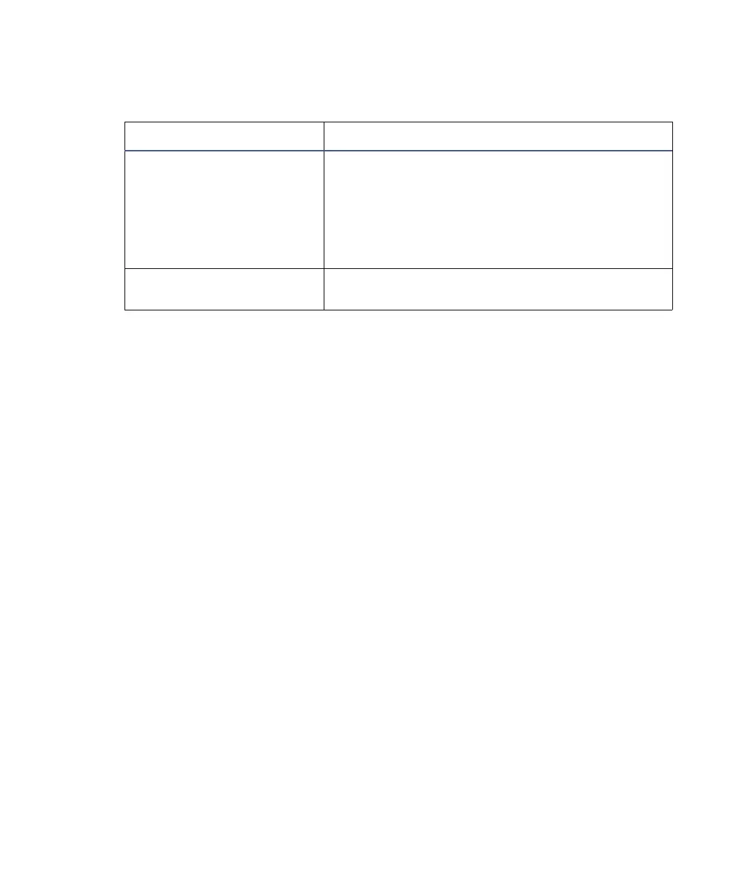
Electrical specifications (Continued)
Item Specification