2-6 Preparing for operation
Configuring 515 pumps
To configure a system that has one or more 515 pumps:
1. Check Enable for 515 (A), 515 (B), and/or 515 (C). They can function
either as contributors to solvent flow A or B, or as non-contributors.
2. Select the GPIB address (for the pump control module) in the “Associate
with an instrument” list.
Tip: You can change the pump names in the Module Name column.
3. Under Configure, click the ellipsis “...” (Browse) in the 515 (A) row.
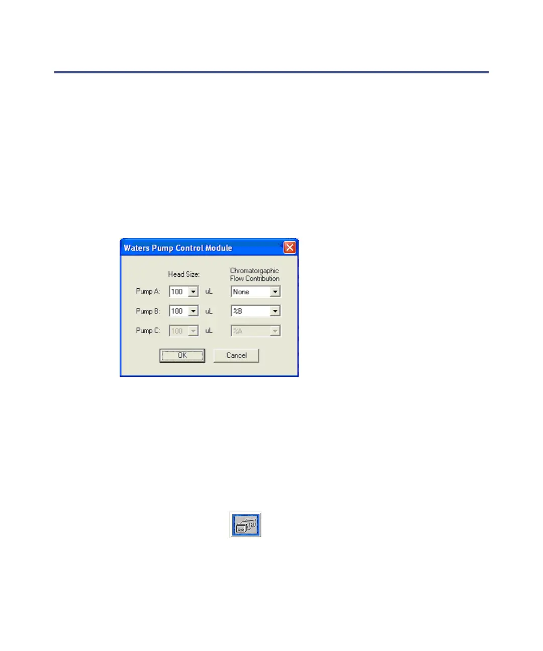
Selecting 515 pump heads and flow contributions
4. For each 515 pump, select the size of the installed pump head.
Values: 50, 100, or 225 µL. The default is 100 µL.
5. Select the chromatographic flow contribution for each 515 pump.
Values: None (a makeup pump), %A (contributes to flow from BGM
pump A), or %B (contributes to flow from BGM pump B).
6. Click OK.
7. Select LC > Reset Communications, and then click Close.
8. Click Inlet Method > (515 Pumps).