June 28, 2016, 715003956 Rev. C
Page 102
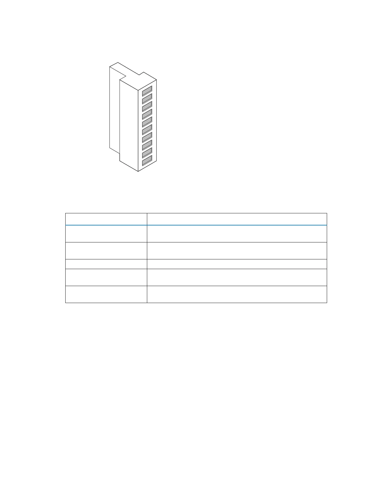
Figure D–17: I/O signal connector
D.11.1 Signal connections
Requirement: To meet the regulatory requirements of immunity from external electrical
disturbances, install connection covers over the signal connectors.
To make signal connections:
1. Reference the signal connection location from the silk-screened label for inject start or any
other input/output connection you plan to use from Connector I or II on the rear panel of
each instrument.
Table D–1: Instrument analog-out/event-in connections
Signal connections Description
Analog (Out) Used for analog chart output functionality. The output voltage
range is 0 to 1 V. The resolution of the voltage output is 12 bits.
Stop Flow (Out) Used to stop the solvent flow if the nitrogen gas supply fails.
Maximum 30 V, 0.5 A, 10 W.
Inject Start (In) Signals the start of an injection. Maximum 30 V.
Event (In) Allows an external device to start data acquisition. Maximum
30 V.
Switch (Out) Used to send time-based contact closure signals to external
devices. Maximum 30 V, 0.5 A, 10 W.
1
2
3
4
5
6
7
8
9
10
+
−
+
−
+
−
+
–
−
+
Stop Flow (Out)
Stop Flow (Out)
Switch (Out)
Switch (Out)
Inject Start (In)
Inject Start (In)
Event (In)
Event (In)
Analog (Out)
Analog (Out)