Maintenance procedures 3-73
2. Pull the position sensing switch out of the stop ring.
3. Insert a new position sensing switch.
4. Reassemble the injector according to the instructions in “Replacing the
rotor seal” on page 3-74.
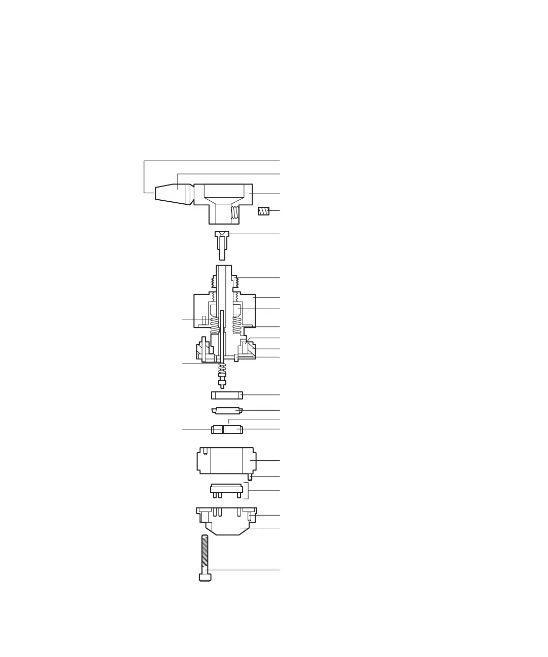
Rheodyne 7725i injector: exploded view
Handle screw
Handle
Needle guide
Set screws (2)
Pressure adjusting screws
Body
Thrust bearing
Spring washers (4)
Rotor pin
Position sensing switch
Stop ring
Seal pins
Needle tube
Bearing ring
Isolation seal
PTFE sleeve
Rotor seal
Stator ring
Stator locating pin
Stator face assembly
Stator locating hole
Stator
Stator screws (3)
Needle seal
Knob