1-8 Overview
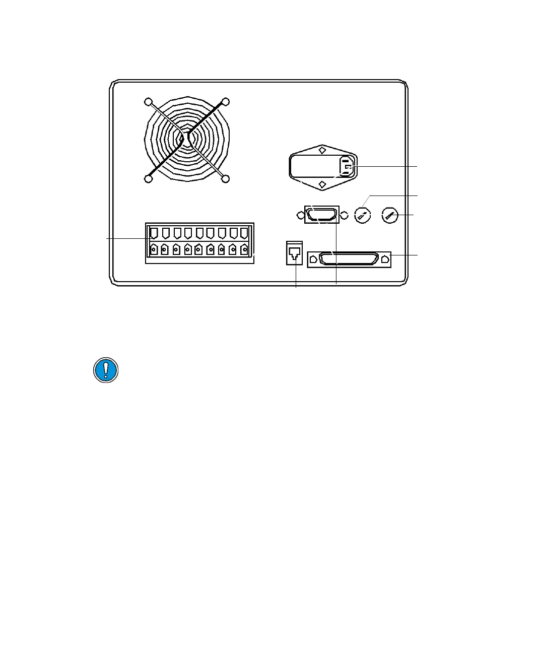
PrepLC controller rear panel
Rear panel
This section describes the electrical connections to the controller’s rear panel.
Event Switches (Connect to terminals S1, S2, S3, S4 and Ground) –
Four switches on the rear panel control column-switching valves, fraction
collectors, or similar external devices that require a contact closure at their
input. These switches, whose maximum current capacity is 1 A each, are
actuated directly or programatically, according to the mode you specify in the
operating software. The controller’s OPERATE METHOD screen allows direct
control of the switches. Program control is through the time-based PROGRAM
EVENT screen, where you must specify each switch as ON, OFF, or PULSE.
Tip: These terminals are always positive with respect to ground: +5 VAC = Off
(open switch); 0 VAC = On (closed switch).
The figure below depicts devices that require a TTL-compatible output
connection.
Caution: Do not use cables longer than 9.8 feet (3 meters) when you
connect to the screw-type barrier terminal strips. Also, attach the cable
shield to the chassis ground of one instrument only
RS-232
connector
IEEE-488
connector
Pump interfac
connector
Auxiliary fuse
Pump fuse
AC power inlet
Plug-in
terminal
receptacles