Watlow F4T Install & Troubleshooting • 9 • Chapter 2 Install and Wire
Wire Size and Torque for Screw Terminations
• 0.0507 to 3.30 mm
2
(30 to 12 AWG) single-wire termination or two 1.31 mm
2
(16 AWG)
• 0.57 Nm (5.0 lb.-in.) torque
Power Requirements
• 85 to 264VÅ (ac), (Models F4T _ _ [1, 2, 3, 4])
• 20.4 to 30.8VÅ (ac) or Î (dc), (Models F4T _ _ [5, 6, 7, 8])
• 50 to 60 Hz
• Power consumption 23W, 54VA
• Inter-module Bus (CX, CY, CZ)
• Do not route network wires with power wires. Connect
inter-module bus wires in daisy-chain fashion when con-
necting multiple devices in a network
• The power supply within the controller base meets all
power requirements for any and all inserted modules.
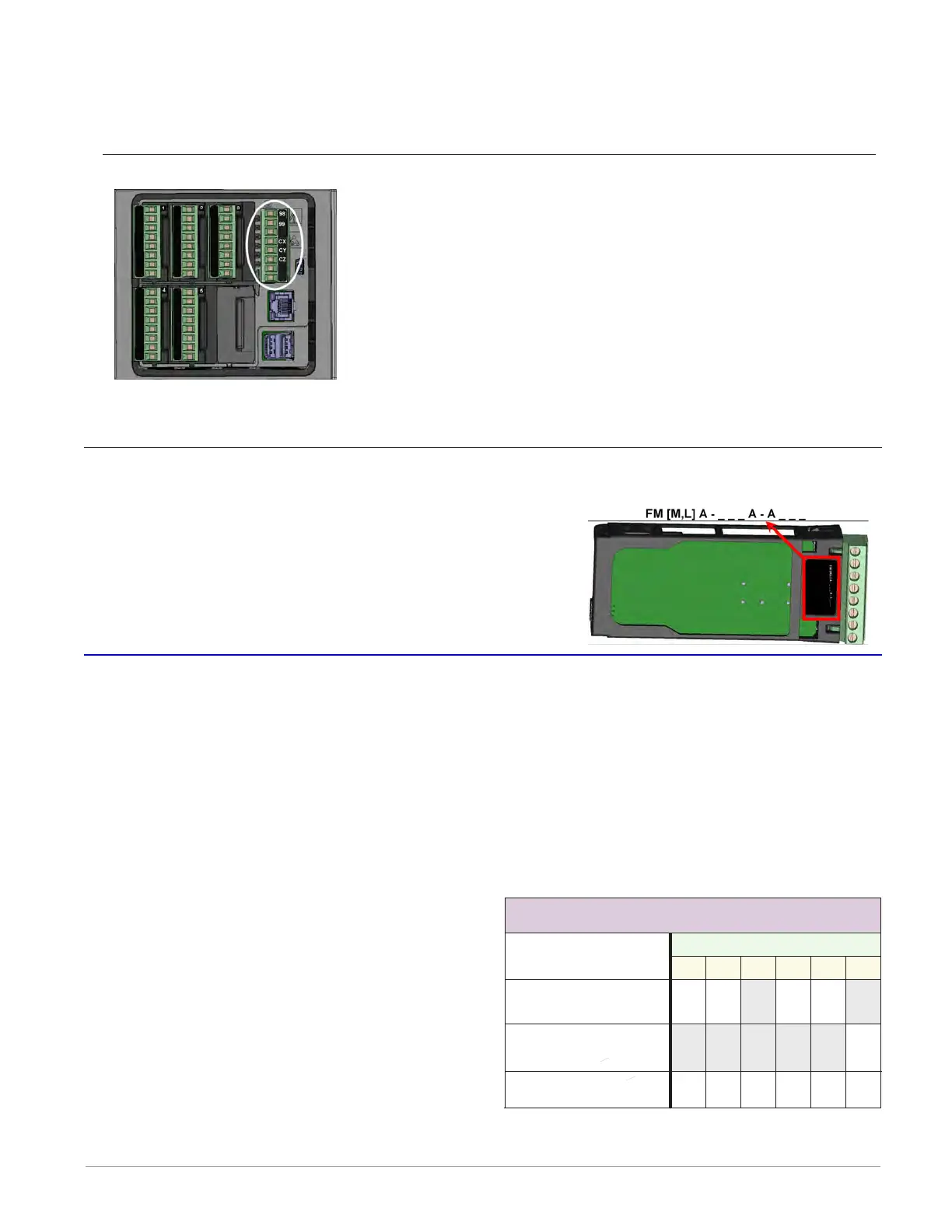
Flex Module (FM) Characteristics
Many of the modules appear to look alike at rst glance, therefore, it is always recommend-
ed that the module part number be noted and veried
prior to plugging it into any of the available slots in a
base. Each module is identied with a part number locat-
ed on the back side of the assembly right below the con-
nector (black label), as seen in the graphic to the right.
Flex Module Installation - To view video go to www.watlow.com/F4T
Some Flex Modules require that they be installed in specic slots within the base. As an
example, if a communications card is to be installed, it must be placed in slot 6. Slot 6 can
receive and accept any card, however, it is the only slot that allows for a communication
card (see table to the right).
Slots are keyed such that modules cannot be inserted upside down. Insert modules with the
component side facing the right when viewing the controller from the rear.
Installing the modules:
1. Note the part number to determine the
types of inputs and outputs available to be
connected in step 7.
2. Turn off power to the controller.
3. Select a slot for the module (see table to
right). If replacing a module, remove the
old module.
4. Afx corresponding slot number labels
(provided) to the module and to the re-
movable screw terminal block.
All Other Modules
Communications
FMCA-(2)
Dual SSR *
FMHA-K
Flex Module - Slot Dependencies
456123
YN
Y
YYYY
NNNN
N = Not allowed
Y = Allowed
Slot #
Module Type
* Reguires two adjacent slots
Anderson-Bolds ~ 216-360-9800

 Loading...


