EasyManuals Logo

Watlow F4T Installation And Troubleshooting User’S Guide

Watlow F4T
59 pages
To Next Page IconTo Next Page
To Previous Page IconTo Previous Page
Page #9 background imageLoading...
Page #9 background image
Watlow F4T Install & Troubleshooting 6 Chapter 2 Install and Wire
Dimensions (cont.)
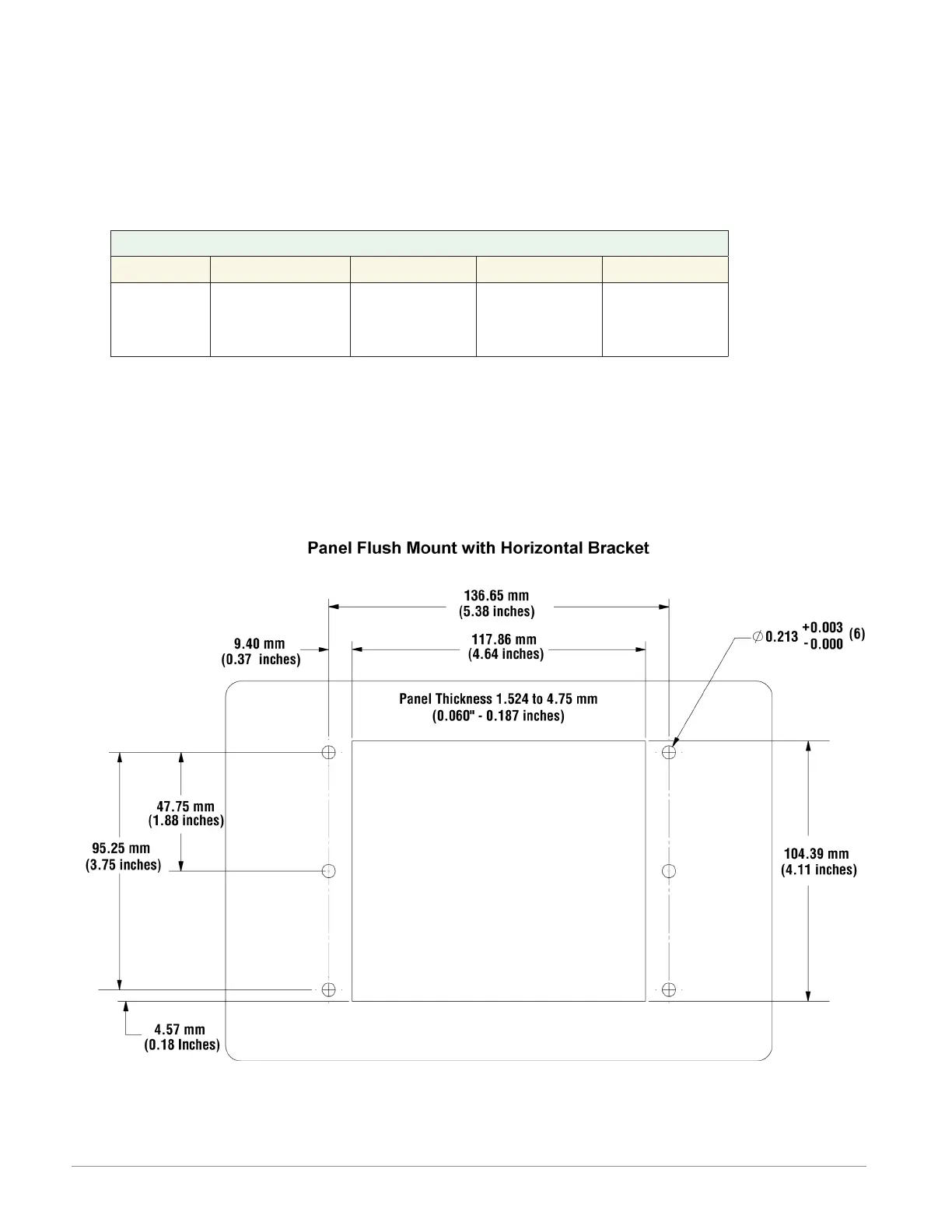
Flush Mounting the Base
1. Fabricate the mounting panel per the ush mount vertical or horizontal panel template
(shown below).
2. Press PEM standoffs (based on panel material) into mounting panel per supplier recom-
mendations.
PEM Standoffs
PEM P/N S0-632-6 Z1 S0S-632-6 S0A-632-6 S04-632-6
Material
Steel
(Zinc Plated)
Stainless
Steel
Aluminum
Hardened
Stainless
Steel
3. Insert the controller through the ush mount bracket and lock it in place with the reten-
tion collar.
4. Mount ush mount bracket to back panel with (6) #6-32 screws.
5. Apply overlay to front panel.
Note:
Overlay is provided by the user.
Anderson-Bolds ~ 216-360-9800
www.anderson-bolds.com

Other manuals for Watlow F4T

Questions and Answers:

Question and Answer IconNeed help?

Do you have a question about the Watlow F4T and is the answer not in the manual?

Watlow F4T Specifications

General IconGeneral
InputsThermocouple, RTD, mA, V
OutputsRelay, SSR, mA, V
CommunicationEthernet, Modbus RTU
Data LoggingYes
CertificationsCE, UL, cUL, RoHS
Control ModesPID, On/Off
Power Supply100 to 240 VAC
Operating Temperature0 to 50°C
Enclosure RatingIP65
Display4.3 in. (109 mm) color touch panel LCD
Control LoopsUp to 4

Related product manuals